AFG5102/Repairs
Battery Module Replacement
The AFG5101/AFG5102 processor board is equipped with a Renata 175-1 battery module which is a common point of failure. This module contains a standard CR2032 Lithium coin cell and two 1N4148 diodes. While the original module is potted in resin, a simple replacement with a battery holder and two 1N4148 diodes can be fabricated.
Gerbers
Pictures
-
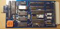
AFG5102 Processor board with water damage and original backup battery module
-
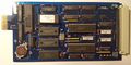
AFG5102 Processor board repaired with new backup battery
-
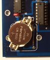
AFG5102 Replacement battery and diodes closeup
-
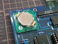
AFG5101 Replacement battery on PCB Module
-
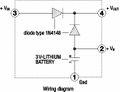
Renata 175-1 schematic and pinout


AFG5101 Display
The front display uses a blue electroluminescent panel for backlighting, which is usually almost completely faded and dim by now, and the LCD contrast is usually quite poor too.
A standard cheap 5-volt Hitachi chipset compatible LCD module with 'parallel' interface can be used as a direct drop-in replacement with the removal of the EL inverter from the rear of the front panel PCB, and the LED backlight to be wired to the supply side of the now-removed EL inverter. Top pad is +ve (to anode). bottom pad is -ve (to cathode).
The new LCD may be 2mm thicker than the original LCD, this can be adjusted for by replacing the original 8 mm tall brass standoffs with 6 mm tall replacement standoffs.
If the contrast is too dark on the new LCD, the contrast pin (third from the left) on the header connector from the front panel PCB to the LCD PCB can be removed entirely, and the connection made with a 3.6 kΩ resistor around the edge of the PCB. This (or a similar value) should bring the contrast back to center scale.
Some 14mm long heat shrink of an appropriate size slipped over the two red LED's (no need to shrink it) will help prevent light bleed from the new LCD causing the LED's to appear illuminated.
To adjust the contrast and turn the backlight on and off, press <SPCL>, then <2> <2> <0> followed by <ENTER>. The contrast can be adjusted using the up and down arrow keys and the backlight turned on and off using the <ENTER> key.
Pictures
-
Replacement LCD installed with resistor mod
