1240
The Tektronix 1240 is a logic analyzer. The 1241 is the same device but with a color-shutter CRT.
Specifications
The 1240/1241 accommodate one to four acquisition boards of type 1240D1 with 9 channels or 1240D2 with 18 channels for a total of up to 72 acquisition channels. Acquisition speeds reach up to 100 MHz asynchronous or 50 MHz synchronous. The 1240/41 provides 14 levels of triggering with conditional branching.
There are two cartridge interfaces. One is for I/O devices; three were produced. The 1200C01 is the RS232C Comm pack. The 1200C02 is the GPIB comm pack. The 1200C11 is the parallel printer comm pack. It required the 12RC01 Printer Support ROM pack. The other cartridge interface was memory specific and was for ROM and RAM packs. Both 8K and 64K RAM packs with battery backup were made, note that the battery is a potential HazMat made by Catalyst Research and may destroy the cartridge when it leaks. There were also ROM packs that allow for mnemonic disassembly and state analysis of most microprocessors of the time. The ROM packs were made with a generic PCB that had two socketed ROMS and jumpers to select the size.
There is a design for a multipurpose RAM/ROM pack, called SuperPack by Pavel Korensky, note the errata in the readme: File:Tek1240-SPDesign10.ZIP
Internals
The 1240 is built around an Intel 8088 as the control processor with 64K DRAM, and firmware in a bank of EPROMs. A separate I/O processor board is powered by a Z80A CPU. The display controller is built from individual TTL and ECL ICs.
The power supply is a switch-mode supply that mainly generates 5 V at up to 45 A. It requires a minimum load of 11.6 A. Additionally it generates 3 V at up to 8 A with no minimum load and several other voltages that are derived from linear post regulators.
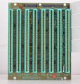
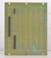
Boards are two to six layers.
The CPU board has battery backed up RAM to save the current configuration and one user config. This battery is a potassium hydroxide electrolyte cell. It will eventually fail and leak, damaging the PCB. The battery is visible on the picture for the A09 processor board.
Links
- Tektronix 1240 / 1241 / 1240D2 @ barrytech.com
- Video showing basic operation
- Video showing GPIB implementation
Pictures
-
Tektronix 1240, front view
-
Rear panel (note second power switch)
-
Tektronix 1241 display
-
Tektronix 1241, front view
-
Tektronix 1241, rear view
-
Side with probe panel
-
1240 self test display
-
1240 state table view
-
1240 timing diagram view
-
Tek 155-0270-00 probe data interface hybrid (one of three)
-
A06 CRT drive board (also includes comms pack interface)
-
A06 CRT drive board (rear side)
-
A07 Power supply
-
A07 Power supply (rear side)
-
A07 Power supply low voltage regulators
-
A08 Interface board
-
A08 Interface board (rear side)
-
A09 Control processor board
-
A09 Control processor board (rear side)
-
A10 I/O processor board
-
A10 I/O processor board (rear side)
-
A11 Display generator board
-
A11 Display generator board (rear side)
-
A14 Trigger board
-
A14 Trigger board (rear side)
-
A15 1240D1 9-channel board
-
A15 1240D1 9-channel board (rear side)
-
1200C02 GPIB COMM PACK
-
ROM PACK
-
1241 State Table View


