TG501: Difference between revisions
Jump to navigation
Jump to search
No edit summary |
(→Specifications: and →Repair Issues: added) |
||
| Line 9: | Line 9: | ||
There is also a TG501A. | There is also a TG501A. | ||
{ | ==Specifications== | ||
* Markers: 5 s to 1 ns in a 1,2,5 sequence | |||
* Marker Amplitude: ≥1V peak on 5s through 10 ns; ≥750 mV<sub>p-p</sub> on 5 ns and 2 ns; ≥ 200 mV<sub>p-p</sub>V on 1 ns - All values into 50 Ohm | |||
*Trigger Output Signal: Slaved to marker output from 5 s through 100 ns . Remains at 100 ns for all faster markers | |||
{| class="wikitable" | |||
! Internal Reference !! Standard - 1MHZ !! Option:1 - 5 MHz | |||
|- | |||
| Stability || 1E-5 || 5E-7 | |||
|- | |||
| Long-Term Drift || 1E-5 per month || 1E-7 per month | |||
|- | |||
| Setability || 1E-7 || 5E-9 | |||
|} | |||
* External Reference Input: 1 MHz; 5 MHz; 10 MHz; TTL compatible (Internally hard wired so output frequencies counted down to 1 MHz) | |||
* Error Readout Range: to ±7,5% | |||
* Error Readout accuracy: One digit (±0,1%-points) | |||
* Net Weight: 1 kg | |||
* Dimensions: 66,8 mm (w/B) x 285,3 mm (d/T) 125,9 mm (h/H) | |||
==Repair Issues== | |||
* Check for +15V and adjust if not between 14,3 V and 15,7 V | |||
* If +5V is not in between 4,94 V and 5,46 V check U626 (LM741 OpAmp). The old OpAmps tend to fail. | |||
* A lot of ICs are placed in non gold plated IC sockets. Contact problems can occure. Removing and inserting ICs helps. | |||
* Mounting of A1 board to frame should be done with washers in between, especially near the rear connector. Shorts to conductor tracks can occure otherwise. | |||
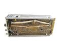
==Pictures== | ==Pictures== | ||
Revision as of 19:22, 21 January 2019

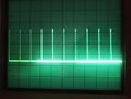
The Tektronix TG501 is a time mark generator plug-in for the TM500 system.
Note the output must be terminated into 50 Ω or there may be no signal at all.
There is also a TG501A.
Specifications
- Markers: 5 s to 1 ns in a 1,2,5 sequence
- Marker Amplitude: ≥1V peak on 5s through 10 ns; ≥750 mVp-p on 5 ns and 2 ns; ≥ 200 mVp-pV on 1 ns - All values into 50 Ohm
- Trigger Output Signal: Slaved to marker output from 5 s through 100 ns . Remains at 100 ns for all faster markers
| Internal Reference | Standard - 1MHZ | Option:1 - 5 MHz |
|---|---|---|
| Stability | 1E-5 | 5E-7 |
| Long-Term Drift | 1E-5 per month | 1E-7 per month |
| Setability | 1E-7 | 5E-9 |
- External Reference Input: 1 MHz; 5 MHz; 10 MHz; TTL compatible (Internally hard wired so output frequencies counted down to 1 MHz)
- Error Readout Range: to ±7,5%
- Error Readout accuracy: One digit (±0,1%-points)
- Net Weight: 1 kg
- Dimensions: 66,8 mm (w/B) x 285,3 mm (d/T) 125,9 mm (h/H)
Repair Issues
- Check for +15V and adjust if not between 14,3 V and 15,7 V
- If +5V is not in between 4,94 V and 5,46 V check U626 (LM741 OpAmp). The old OpAmps tend to fail.
- A lot of ICs are placed in non gold plated IC sockets. Contact problems can occure. Removing and inserting ICs helps.
- Mounting of A1 board to frame should be done with washers in between, especially near the rear connector. Shorts to conductor tracks can occure otherwise.
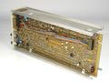
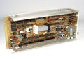
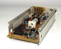
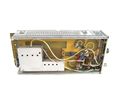
Pictures
-
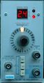
TG501 Early Version
-
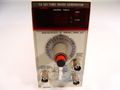
TG501 Late Version
-
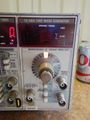
TG501A
-
-
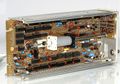
TG501
-
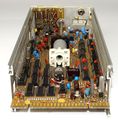
TG501
-
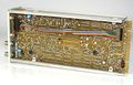
TG501
-
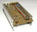
TG501
-
TG501
-
TG501
-
TG501
-
TG501 early version
-
TG501 early version


