067-1264-00
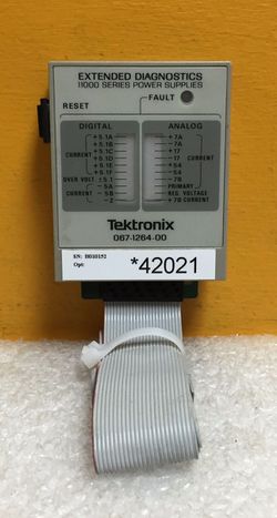
The Tektronix 067-1264-00 11000 Series Power Supplies Extended Diagnostics Test Fixture is a power supply diagnostics fixture for 11000-series scopes. It was designed by Steve Pepper, who also designed the power supply used in 11k scopes. The manufacturing engineer who built the 067-1264-00 units was Mike Foley.
Description of the 067-1264-00 by its designer, Steve Pepper
Theory of Operation
All 11k mainframe power supplies share the same block diagram and share common diagnostic features. All have multiple DC outputs, and each output has current sensing. Over-current, or over-voltage faults on any of the outputs cause the power supply to shut down gracefully, and attempt restarts at ~1sec intervals.
Purpose of the Test Fixture
Because the faults are cleared by the shutdown, the FAULT condition is very brief relative to the restart period. A ‘scope would be required to diagnose which of the 20+ possible fault detectors is triggering the restart. To diagnose without a ‘scope, the fault signals need to be latched, so they can keep an LED lit for the duration of the restart interval. That task is performed by the 11k Power Supply Test Fixture with unijunction transistors serving as latches.
Overvoltage
Since all the supplies are derived from the same transformer, and they don't have separate shut-down mechanisms, only one overvoltage sensor is needed on the primary output. The "analog" voltages with post-regulators do not use "foldback" current limiting, since any fault will shut down all supply voltages simultaneously, separate overvoltage sensors are not provided.
Operation
The detector outputs are routed to a common diagnostic port accessible from outside the mainframe. The test fixture has 20+ channels, a FAULT LED, and a RESET button. It can be attached at any time “live” or in standby without the need to cycle power. The test fixture is powered by the mainframe “housekeeping” supply. Use the RESET button to clear the previously latched condition. The LED corresponding to the fault condition should remain lit. If no indicators are lit but the FAULT remains lit this indicates a fault condition not caused by over current or overvoltage that will have to be diagnosed within the supply itself with the help of a schematic and a ‘scope.


