180
The Tektronix 180A was introduced in 1958 and is an all-tube time mark generator with an oven-controlled crystal oscillator (OCXO). It was designed by Rodgers Jenkins.
Time mark generators put out pulses at user-selectable intervals. They are primarily used for calibrating the time-base of oscilloscopes. Switches on the front panel select which of the divided-down pulse signals will be added together to form the output waveform. The Tektronix 180 has toggle switches. The 180A has pushbutton switches.
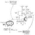
The signal path of the 180A starts with an OCXO producing 1 MHz, which is then divided down using synchronized monostable multivibrators. This scheme does not require precision in the time constant of the monostable multivibrators. The only precision component in the 180A is the OCXO (part number 158-007).
In addition to the time mark generator functionality, the 180A also produces sine waveforms at 5 MHz, 10 MHz, and 50 MHz. These frequencies are produced by feeding the 1 MHz OCXO output to a series of three frequency multipliers. First the 1 MHz is quintupled to get the 5 MHz signal. Then the 5 MHz signal is doubled to the 10 MHz signal. Then the 10 MHz signal is quintupled, yielding the 50 MHz signal. Each of the three frequency multipliers is composed of a 6DK6 pentode driving an LC resonator tuned to 5 MHz, 10 MHz, and 50 MHz.
The 180A manual suggests an interesting procedure for calibrating the OCXO, by attaching a small antenna to deliberately interfere with the national time standard broadcast, and observing the interference with a communication receiver.
The method is to zero-beat the WWV standard frequency broadcast with the internal crystal oscillator to align the OCXO frequency. First tune ham receiver to WWV broadcast - say 10 MHz - and watch the audio subtone using an oscilloscope connected to the audio out of the receiver. Then wait for specific minutes of the hour where there is no audio subtone in WWV. Then select 1 μs output on 180A, which will have 10 MHz as the harmonic. Connect a wire from the output of the 180A as an antenna and couple it to the antenna input of the receiver. This way, the 10 MHz WWV and 10 MHz harmonic from the 180A will beat in the receiver input, and the difference will be visible as a wave in the oscilloscope. Then adjust C105 to align the crystal frequency so close to the reference WWV 10 MHz that the frequency difference becomes zero or the waveform on the scope becomes flat.
You could also use the S-Meter in the receiver instead of the oscilloscope to perform the same.
The 180A, serial number 5599 and up, uses the 120-119 power transformer.
Key Specifications
- please add
See Also
Pictures
180
180A
External
-
Tel 180A Front Panel #1
-
Tek 180A Front Panel #2
-
Tek 180A Front Panel #3
-
Tek 180A Front
-
Tek 180A Front
-
Tek 180A Rear
-
Tek 180A Top
-
Tek 180A
-
Tek 180A Rear
Internals
-
Tek 180A Top w/o Cover
-
180A Internal - Tubes
-
Tek 180A Internal - Power Supply/Transformer
-
Tek 180A Internal - Main Chassis
-
Tek 180A Internal - Power Supply Tubes
-
Tek 180A Internal - Switches
-
Tek 180A Under Chassis w/o Cover
-
Tek 180A Internal Tubes Live
-
Tek 180A Rear w/o Air Filter
-
180A internal
-
180A internal
-
180A internal
RM180A
-
180A-RM in black
-
180A-RM in black
Schematics
-
180A Block Diagram
-
Oscillator circuit in 180A using 158-007
-
late sn power supply


