EG&G N-AM-171

The EG&G N-AM-171 is a third-party 7000-series plugin that appears to be based on a Tektronix 7A17.
Key Specifications
- please add
See also
Interrnals
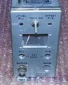
It has a 3 section BCD switch whose output is decoded and is readout on the upper position for its slot. The "clamp" switch causes the word CLAMP to be readout on the lower slot position.
Dennis Tillman says,
The circuit is very simple. It does not use any of the built-in interface/amplifier of the 7A17 plugin. [...]
The heart of it appears to be 3 relays. There are two small DPDT relays and an SPDT RF relay, which has a 48 volt coil. Aside from the thumbwheel switches which have a lot of resistors on the back of them, there isn't much else.
The connector labeled WORM on the front panel goes to one BNC connector of the RF relay, a terminator is on another BNC connector of the relay, and the third BNC connector of the relay goes to pin B-11 (I think) of the rear connector of the plugin.
The connector labeled MARKER goes to A-11 of the rear connector (or thereabouts). So both of these probably act as a differential signal for the scope’s vertical amplifier chain.
I fed a signal into MARKER and it was displayed on the scope faithfully. When I fed that signal into the WORM input I got no indication on the scope so I may have to activate one of the B/L or P/B inputs for this to latch the RF relay in the right direction.
The only output from all the resistors on the back of the thumbwheel switches appears to be two wires that go to A31 and B31. These generate a readout on the top row of the scope that says INd followed by two digits that correspond to whatever the thumbwheels were dialed to. For example if the thumbwheels are set to 34 then INd34 would appear on the top readout row.
The connector marked B/L goes to one of the DPDT relays and the connector marked P/B goes to the other DPDT relay. The B/L and P/B input signals appear to be connected to the coil of their respective DPDT relays. The EXT CLOSE label between these two inputs suggests to me that they provide a way to close the DPDT relays via an external signal. A wire going from one of the two DPDT relays appears to connect the RF relay's coil to 50 Volts to activate it.
The POSITION knob on my plugin didn't seem to do anything. It didn't move the trace up or down.
The timebase needed an external trigger to sync so this plugin doesn't appear to provide a trigger signal.
Pictures
-

N-AM-171
-
N-AM-171 carcass
