567: Difference between revisions
No edit summary |
No edit summary |
||
| Line 12: | Line 12: | ||
* [http://w140.com/tek_readout_oscilloscopes_1968_catalog.pdf "Digital Readout Introduction" in 1968 Catalog (PDF)] | * [http://w140.com/tek_readout_oscilloscopes_1968_catalog.pdf "Digital Readout Introduction" in 1968 Catalog (PDF)] | ||
}} | }} | ||
The Tektronix 567 is a [[sampling oscilloscope]] | The '''Tektronix 567''' is a [[sampling oscilloscope]] mainframe [[introduced in 1962]]. | ||
It has a digital plug-in unit, the [[6R1]] or [[6R1A]], that can be used to measure | It has a digital plug-in unit, the [[6R1]] or [[6R1A]], that can be used to measure | ||
waveform characteristics such as rise time. This digital unit provides a go/no-go output | waveform characteristics such as rise time. This digital unit provides a go/no-go output | ||
| Line 55: | Line 55: | ||
useful for measuring the peak-to-peak amplitude of a signal. | useful for measuring the peak-to-peak amplitude of a signal. | ||
The mechanisms used by the digital unit are a sample and hold | The mechanisms used by the digital unit are a sample and hold circuit, a comparator, a counter, and a switched tap voltage divider. | ||
circuit, a comparator, a counter, and a switched tap voltage divider. | The digital unit takes its input from the vertical signal produced by the sampling unit. Therefore, it operates on a low-speed signal, | ||
The digital unit takes its input from the vertical signal produced | somewhat similar to the intermediate frequency (IF) in a superheterodyne radio. | ||
by the sampling unit. Therefore, it operates on a low-speed | |||
signal, somewhat similar to the intermediate frequency (IF) in | The user of the 567 positions two cursors along the X-axis. These cursors define two times and two voltages. | ||
a superheterodyne radio. The user of the 567 positions two | The tapped voltage divider produces several voltages along the interval spanned by the two cursor voltages: | ||
cursors along the X-axis. These cursors define two times and | 10%, 20%, 27%, 50%, 73%, 80%, and 90%. These voltages are used for making measurements such as the 10%-to-90% rise time. | ||
two voltages. The tapped voltage divider produces several | In this case, a counter is reset and started when the signal passes through the 10% voltage. | ||
voltages along the interval spanned by the two cursor voltages: | The counter counts the number of cycles of a built-in crystal clock. When the signal reaches the 90% voltage, | ||
10%, 20%, 27%, 50%, 73%, 80%, and 90%. These voltages are used | the counter is stopped and the count is displayed on the [[nixie tube]] digital numeric readout. The units and decimal place of the | ||
for making measurements such as the 10%-to-90% rise time. In this | digital unit are controlled by switch contacts on the timing unit plug-in, which connect to the digital unit through a multi-pin connector in the 567. | ||
case, a counter is reset and started when the signal passes through | |||
the 10% voltage. The counter counts the number of cycles of a | |||
built-in crystal clock. When the signal reaches the 90% voltage, | |||
the counter is stopped and the count is displayed on the [[nixie | |||
tube]] digital numeric readout. The units and decimal place of the | |||
digital unit are controlled by switch contacts on the timing unit plug-in, | |||
which connect to the digital unit through a multi-pin connector in | |||
the 567. | |||
The 567 does not have any post-deflection acceleration of the beam. | The 567 does not have any post-deflection acceleration of the beam. | ||
| Line 86: | Line 78: | ||
to be operated outside the plug-in bay of the 567 for maintenance purposes. | to be operated outside the plug-in bay of the 567 for maintenance purposes. | ||
{{MissingSpecs}} | |||
==Pictures== | ==Pictures== | ||
<gallery> | <gallery> | ||
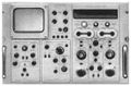
567_front.jpg|Front view, w 6R1A digital unit | |||
567_front_6r1.jpg | Front view, w 6R1 digital unit | |||
Tek_567_introduction2.jpg|576 Introduction in 1962 Catalog | |||
Tek567-3s76-3t77.jpg | |||
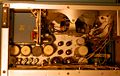
Tek 567 ps top.jpg|Top view power supply. Blue capacitors are not original. | |||
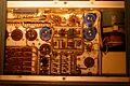
Tek 567 plug-in bay.jpg|Plug-in bay | |||
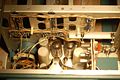
Tek 567 ps bottom.jpg|Bottom view power supply | |||
Tek 567 plug-in connectors.jpg|Plug-in connectors rear | |||
Tek 567 plug-in connectors2.jpg|Plug-in connectors front | |||
S52 s4 567.jpg|567 measuring 37ps combined rise time of [[S-52]] and [[S-4]] | |||
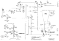
Tek-567 interconnections.png|Interconnections | |||
Tek-567 power supply.png|Power Supply | |||
Tek-567 calibrator.png|Calibrator | |||
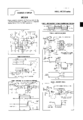
Tek-567 crt circuit.png|CRT Circuit | |||
Motorola mc314.png|Motorola MC314 Datasheet Specifying Tek 567 for Timing Measurements | |||
Tek rm 567 small.jpg|Rackmount Version, the RM 567 | |||
</gallery> | </gallery> | ||
Revision as of 12:37, 15 May 2017

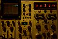
The Tektronix 567 is a sampling oscilloscope mainframe introduced in 1962.
It has a digital plug-in unit, the 6R1 or 6R1A, that can be used to measure waveform characteristics such as rise time. This digital unit provides a go/no-go output based on waveform characteristics. This feature makes the 567 particularly useful in production testing for tasks such as binning logic gates based on their speed.
The 567 came after the 661 and before the 568 and its associated 230 Digital Unit.
According to Stan Griffiths,
It looks like there were two different serial number runs of 567's.
Bench models:
- 000101-000750 = 650 instruments
- 002000-003280 = 1280 instruments
- Total = 1930
Rackmount models:
- 000101-000228 = 128 instruments
- 002000-002240 = 240 instruments
- Total = 368
Grand Total = approx. 2300
The 567 has three plug-in compartments. The left compartment holds a 3S-series sampling vertical unit such as a 3S2. The center compartment holds a 3T-series sampling sweep unit such as a 3T77. The right compartment holds the digital unit, either a 6R1 or a 6R1A. It is possible to operate a 567 without the digital unit but in that configuration it provides only the functionality that a 561 provides.
The 6R1 and 6R1A digital units have several different operating modes. These modes can be classified as time measurement or voltage measurement. One time measurement mode, for example, shows the time delay between the rising pulse edge on input A and the falling pulse edge on input B. This is useful for measuring the speed of a logic gate such as an inverter. One of the voltage measurement modes displays the difference between the input A voltage at on time and the input A voltage at some other time. This is useful for measuring the peak-to-peak amplitude of a signal.
The mechanisms used by the digital unit are a sample and hold circuit, a comparator, a counter, and a switched tap voltage divider. The digital unit takes its input from the vertical signal produced by the sampling unit. Therefore, it operates on a low-speed signal, somewhat similar to the intermediate frequency (IF) in a superheterodyne radio.
The user of the 567 positions two cursors along the X-axis. These cursors define two times and two voltages. The tapped voltage divider produces several voltages along the interval spanned by the two cursor voltages: 10%, 20%, 27%, 50%, 73%, 80%, and 90%. These voltages are used for making measurements such as the 10%-to-90% rise time. In this case, a counter is reset and started when the signal passes through the 10% voltage. The counter counts the number of cycles of a built-in crystal clock. When the signal reaches the 90% voltage, the counter is stopped and the count is displayed on the nixie tube digital numeric readout. The units and decimal place of the digital unit are controlled by switch contacts on the timing unit plug-in, which connect to the digital unit through a multi-pin connector in the 567.
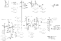
The 567 does not have any post-deflection acceleration of the beam. The CRT circuit uses two 5642 high-voltage rectifier tubes, one (V822) to generate the CRT cathode voltage (-3,300 V) and one (V832) to generate the CRT grid bias voltage. CRTs used were T5032 (earlier) and T5611 (later models).
A 567 can be perform remotely controlled measurements by connecting a 262 programmer to the 6R1 or 6R1A that is in the 567.
There is an extender plug-in, the 067-0505-00, that allows a 6R1 or 6R1A to be operated outside the plug-in bay of the 567 for maintenance purposes.
Key Specifications
- please add
Pictures
-
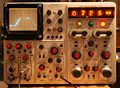
Front view, w 6R1A digital unit
-
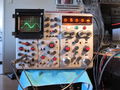
Front view, w 6R1 digital unit
-
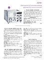
576 Introduction in 1962 Catalog
-

-
Top view power supply. Blue capacitors are not original.
-
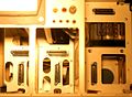
Plug-in bay
-
Bottom view power supply
-
Plug-in connectors rear
-
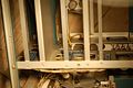
Plug-in connectors front
-
-
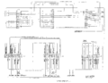
Interconnections
-
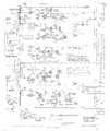
Power Supply
-
Calibrator
-
CRT Circuit
-
Motorola MC314 Datasheet Specifying Tek 567 for Timing Measurements
-
Rackmount Version, the RM 567


