491: Difference between revisions
No edit summary |
No edit summary |
||
| Line 17: | Line 17: | ||
}} | }} | ||
<center> NOTE: Due to severe performance limitations, it was replaced by the completely redesigned 492 in 1980 </center> | <center> NOTE: Due to severe performance limitations, it was replaced by the completely redesigned 492 in 1980 </center> | ||
<center>TEST</center> | |||
--------------------------------------------------------- | --------------------------------------------------------- | ||
Revision as of 17:47, 7 July 2019
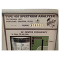
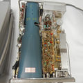
The Tektronix 491 is a spectrum analyzer with a frequency range of 10 MHz to 40 GHz. The minimum resolution bandwidth is 1 kHz, and provides measurement resolution proportional to the frequency accuracy or span.
Front panel inputs/outputs are: RF INPUT (A) BNC connector (50Ω, 10 MHz to 275 MHz); RF INPUT (B) N connector (50Ω, 275 MGHz to 2 GHz); WAVEGUIDE (C) N connector (50Ω; 12.4 GHz to 40 GHz); and a dual function 1 MHz MARKERS OUT BNC connector (With the INT REF FREQ in the ON position a 1 MHz marker outputs to this connector. With the INT REF FREQ in the OFF position EXT REF FREQ IN “same” BNC connector accepts an external signal between 1 MHz and 5 MHz (1 to 5 V peak to peak) applied to the connector becomes the reference frequency for the phase lock operation).
Rear panel inputs/outputs are: TRIG IN BNC connector (20 Hz to 100 kHz, ≥0.2V); SAW OUT BNC connector (75mV/div); and RECORDER BNC connector (≥4 mV/div of displayed signal in LIN mode, DC-coupled, into 600Ω load impedance).
Specifications based on final published documentation, unless otherwise specified.
Key Specifications
| Frequency Range |
CAUTION: Signals stronger than +15 dBm applied to the input or mixer will damage or burn out the mixer diodes |
|---|---|
| Dispersion Range (plus 0 Hz) | 200 kHz/div to 10 MHz/div in 1-2-5 sequence |
| Resolution Bandwidth Range | 6 dB bandwidths from 1 kHz to 100 kHz |
| RF Input impedance | 50 Ω |
| Maximum Safe Input Power | -30 dBm for linear operation and +15 dBm (25 mW) diode mixer power limit |
| IF Attenuator Range | 0 dB to 51 dB, in combinations of 1, 2, 4, 8, 16, and 20 dB |
| Sweep Speed Range | 0.5 s/div to 10 µs/div in 1, 2, 5 sequence; Uncalibrated to approx 1.25 s/div |
| Triggering Modes | Internals, External, and Line. 100 V maximum input (DC + peak AC) |
| Display Dynamic Range | ≥40 dB |
| Dynamic Range | 80 dB (Max sensitivity of -110 dBm minus Max input power of -30 dBm) |
| Calibrator Frequency | 200 MHz |
| Included Accessories | Two Instruction Manuals; 6-ft, 50Ω coaxial cable, BNC-BNC; 6-ft, 50Ω coaxial cable, N-N; 2-ft, 50Ω coaxial cable, TNC-TNC; 12.4 GHz to 18 GHz waveguide mixer; 18 GHz to 26.5 GHz waveguide mixer; 26.5 to 40 GHz waveguide mixer; 10 dB attenuator N type fittings; 20 db attenuator N type fittings; two BNC male to N female adapters; two BNC female to N male adapters; Waveguide mixer adapter; power cord; dust and rain cover; 3 to 2 wire adapter; blue light filter; amber light filter; clear CRT protector plate; ornamental ring; mesh filter (installed); two one-ampere fuses; and 1/2 –ampere fuse |
| Weight | Portable: 13.6 kg (30 lbs) ; Rackmount: 18 kg (40 lbs) |
| Power | 90 − 136 VAC in three ranges, 48 to 440 Hz; 180 – 272 VAC in three ranges, 48 to 440 Hz. At 115 VAC, 60 Hz, 55 W |
| Operating Atmospherics | Temperatures: -15 °C to +55 °C; Humidity: Five cycles (120 hours) of MIL-STD-202C Method 106B; Altitude: Up to 4.6 km (15,000 ft) |
Options
- Opt. 01: Limit Frequency Range to 10 MHz to 2 GHz
- Opt. 02: Limit Frequency Range to 1.5 GHz to 40 GHz


