DF1: Difference between revisions
No edit summary |
(more relevant key specs) |
||
| Line 17: | Line 17: | ||
* [http://w140.com/smb/df1_sm.pdf Tektronix DF1 Manual] (OCR) | * [http://w140.com/smb/df1_sm.pdf Tektronix DF1 Manual] (OCR) | ||
}} | }} | ||
The '''Tektronix DF1''' is a display formatter for use with the [[7D01]] logic analyzer. It adds "data domain displays" (binary, octal and hexadecimal state tables, and a function map display) to the 7D01's time-domain display. It can store a reference table, to which the captured data can be compared. | The '''Tektronix DF1''' is a display formatter for use with the [[7D01]] logic analyzer. It adds "data domain displays" (binary, octal and hexadecimal state tables, and a function map display) to the 7D01's time-domain display. It can store a reference table, to which the captured data can be compared. The [[DF2]] is essentially a DF1 with an extra key ("Menu") and additional ROM supporting GPIB diagnostics. | ||
Project manager for the DF1 was [[Murlan Kaufman]]. | Project manager for the DF1 was [[Murlan Kaufman]]. | ||
| Line 24: | Line 24: | ||
{{BeginSpecs}} | {{BeginSpecs}} | ||
{{Spec | | {{Spec | Memory | One reference table memory, same as 7D01 capacity (max. 16 channels at 254 bits/ch) }} | ||
{{Spec | Display modes | | |||
* State table: Hexadecimal, octal, or binary formats; two tables (reference, 7D01 memory) of 17 lines of 16-bit words | |||
{{Spec | Display | | * Map: Dot display of the 16 data channels in X-Y coordinate points. Each dot location represents one possible combination of up to 16 inputs to the 7D01/ | ||
* | * Timing: Standard 7D01 display – 4, 8 or 16 bits | ||
* | }} | ||
* | {{Spec | Reset output | Positive 100 μs pulse, ≤0.4 V / ≥2.4 V }} | ||
{{Spec | | |||
{{EndSpecs}} | {{EndSpecs}} | ||
| Line 41: | Line 37: | ||
==Pictures== | ==Pictures== | ||
<gallery> | <gallery> | ||
Tek df1 front.JPG|Front | Tek df1 front.JPG|Front | ||
Revision as of 11:02, 9 January 2022

The Tektronix DF1 is a display formatter for use with the 7D01 logic analyzer. It adds "data domain displays" (binary, octal and hexadecimal state tables, and a function map display) to the 7D01's time-domain display. It can store a reference table, to which the captured data can be compared. The DF2 is essentially a DF1 with an extra key ("Menu") and additional ROM supporting GPIB diagnostics.
Project manager for the DF1 was Murlan Kaufman.
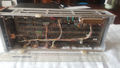
The DF01 attaches to the 7D01 through a 50-pin D-sub connector on the right side panel only, it has no direct connection to the scope mainframe. The DF1 and 7D01 are mechanically coupled by three nylon standoffs that slide into cutouts in the 7D01's case rails. The bottom two standoffs are fixed and are inserted first, then the connector is plugged in and the third, sliding, stand-off at the top is moved to its locked position.
Key Specifications
| Memory | One reference table memory, same as 7D01 capacity (max. 16 channels at 254 bits/ch) |
|---|---|
| Display modes |
|
| Reset output | Positive 100 μs pulse, ≤0.4 V / ≥2.4 V |
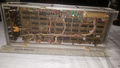
Internals
The DF1 is built around a Motorola 6800 microprocessor with two 2K×8 masked ROMs and sixteen 1K×1 SRAMs (2101).
Pictures
-
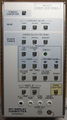
Front
-
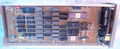
Internal
-

-

Side connector
-
-
-

-


Custom ICs used in the DF1
No results