DC505: Difference between revisions
No edit summary |
No edit summary |
||
| Line 33: | Line 33: | ||
! Signal | ! Signal | ||
|- | |- | ||
| | | || || 27A || Internal Scan Clock Disable | ||
|- | |- | ||
| 26B | | 26B || Manual Start-Stop || 26A || /RESET | ||
|- | |- | ||
| 25B || Internal Scan Clock Out || 25A | | 25B || Internal Scan Clock Out || 25A || Time Slot Zero | ||
|- | |- | ||
| 24B | | 24B || Internal Scan Clock Out || || | ||
|- | |- | ||
| 23B | | 23B || Overflow || || | ||
|- | |- | ||
| 21B | | 21B || BCD output 2 || || | ||
|- | |- | ||
| 20B | | 20B || BCD output 8 || 20A || BCD output 4 | ||
|- | |- | ||
| 19B | | 19B || Data Good || 19A || BCD output 1 | ||
|- | |- | ||
| | | || || 14A || Ext Clock Input | ||
|} | |} | ||
</small> | </small> | ||
| Line 60: | Line 60: | ||
The first counter decade is implemented as a divide-by-2 ECL flip-flop (U342, MC1670) followed by a five-stage ring counter made with MC10131 ECL flipflops, and some logic to BCD-encode the count result. A similar circuit exists in the reference divider chain. | The first counter decade is implemented as a divide-by-2 ECL flip-flop (U342, MC1670) followed by a five-stage ring counter made with MC10131 ECL flipflops, and some logic to BCD-encode the count result. A similar circuit exists in the reference divider chain. | ||
In the power supply, the | In the power supply, a 723 regulator provides +5 V from the 17.5 V<sub>AC</sub> mainframe rails using the mainframe's NPN pass transistor. Its output includes a zener/SCR crowbar circuit. Another 723 provides +15 V from the +33 V rail. A discrete regulator using the PNP pass transistor produces –10 V from the –33 V rail. | ||
==Pictures== | ==Pictures== | ||
Revision as of 06:15, 4 March 2024

The Tektronix DC505 is a 225 MHz counter/timer plug-in for the TM500 system.
It was superseded by the DC505A in 1976.
Key Specifications
| Frequency range | 0 Hz (DC coupled) / 10 Hz (AC coupled) to 225 MHz |
|---|---|
| Sensitivity | 50 mVRMS to 150 MHz, 100 mVRMS to 225 MHz (sine) |
| Resolution | 7 digits |
| Gate time | 0.01 s to 10 s in decade steps |
| Stability | Standard: 1×10⁻⁵; Opt.1: 5×10⁻⁷ (0°C to +50°C, after 30 min warm-up) |
| Long-term drift | Standard: 1×10⁻⁵ per month; Opt.1: 5×10⁻⁷ per month |
| Features |
|
| Options |
|
Links
Documents Referencing DC505
| Document | Class | Title | Authors | Year | Links |
|---|---|---|---|---|---|
| 070-2088-00.pdf | Book | TM500 Series Rear Interface Data Book | 1975 | AF501 • AM501 • AM502 • DC501 • DC502 • DC503 • DC504 • DC505 • DC505A • DM501 • DM502 • FG501 • FG502 • FG503 • MR501 • PG501 • PG502 • PG505 • PG506 • PG508 • PS501 • PS502 • PS503 • PS503A • PS505 • RG501 • SC501 • SC502 • SG502 • SG503 • TG501 | |
| 070-2088-01.pdf | Book | TM500 Series Rear Interface Data Book | 1976 | AF501 • AM501 • AM502 • AM511 • DC501 • DC502 • DC503 • DC504 • DC505 • DC505A • DD501 • DM501 • DM502 • FG501 • FG502 • FG503 • FG504 • LA501 • MR501 • PG501 • PG502 • PG505 • PG506 • PG508 • PS501 • PS502 • PS503 • PS503A • PS505 • RG501 • SC501 • SC502 • SG502 • SG503 • SG504 • SW503 • TG501 • TR501 • TR502 |
Rear Interface
| Connector Pin | Signal | Connector Pin | Signal |
|---|---|---|---|
| 27A | Internal Scan Clock Disable | ||
| 26B | Manual Start-Stop | 26A | /RESET |
| 25B | Internal Scan Clock Out | 25A | Time Slot Zero |
| 24B | Internal Scan Clock Out | ||
| 23B | Overflow | ||
| 21B | BCD output 2 | ||
| 20B | BCD output 8 | 20A | BCD output 4 |
| 19B | Data Good | 19A | BCD output 1 |
| 14A | Ext Clock Input |
Data is output serially by digit.
Internals
An internal VCO, phase-locked to the 1 MHz master, produces a 100 MHz input to the counter chain for timing measurements.
The DC505 uses a mix of ECL and TTL dividers and logic, and a Mostek MK5007 four-decade counter/latch/multiplexer (U700). Unlike the similarly-specified 7D15, it employs no Tek made custom ICs. The first counter decade is implemented as a divide-by-2 ECL flip-flop (U342, MC1670) followed by a five-stage ring counter made with MC10131 ECL flipflops, and some logic to BCD-encode the count result. A similar circuit exists in the reference divider chain.
In the power supply, a 723 regulator provides +5 V from the 17.5 VAC mainframe rails using the mainframe's NPN pass transistor. Its output includes a zener/SCR crowbar circuit. Another 723 provides +15 V from the +33 V rail. A discrete regulator using the PNP pass transistor produces –10 V from the –33 V rail.
Pictures
-
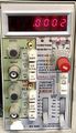
DC505
Components
Some Parts Used in the DC505
| Part | Part Number(s) | Class | Description | Used in |
|---|---|---|---|---|
| 2N4249 | 151-0342-00 | Discrete component | PNP Si low noise amp. | DC501 • DC502 • DC503 • DC503A • DC504 • DC504A • DC505 • DC505A • DC508 • DC508A • DC509 • DC510 |
| Mostek MK5007 | 156-0409-00 | Monolithic integrated circuit | four-decade BCD counter with latches and output multiplexer | 213 • DC505 • DC505A |