1A4: Difference between revisions
(test for improved template) |
No edit summary |
||
| (31 intermediate revisions by 6 users not shown) | |||
| Line 1: | Line 1: | ||
{{Plugin Sidebar | {{Plugin Sidebar | ||
|manufacturer=Tektronix | |||
summary=50 MHz quad input amplifier plugin | | |series=500-series scopes | ||
image=1a4 front. | |type=1A4 | ||
caption=Tektronix 1A4 front | |summary=50 MHz quad input amplifier plugin | ||
|image=Tek 1a4 front.jpeg | |||
introduced=1967 | | |caption=Tektronix 1A4 front | ||
discontinued=1974 | | |introduced=1967 | ||
|discontinued=1974 | |||
|designers=Al Allworth | |||
* [ | |manuals= | ||
* [[Media:070-0545-00.pdf|Tektronix 1A4 Manual]] | |||
* [[Media:Tek 1a4 fcp jan 1967.pdf|Tektronix 1A4 Factory Calibration Procedure, January 1967]] | |||
* [[Media:Tek 1a4 mods.pdf|Tektronix 1A4 Product Modification Index]] | |||
}} | }} | ||
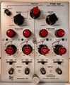
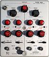
The '''Tektronix Type 1A4''' is a 1-series vertical plug-in for [[ | The '''Tektronix Type 1A4''' is a 1-series vertical plug-in for [[500-series scopes]]. | ||
It has four input channels and 50 MHz bandwidth. | It has four input channels and 50 MHz bandwidth. | ||
Type 1A4 was [[introduced in 1967]] and lasted until the end of the [[500-series scopes]] line. | |||
The four channels are grouped into two groups of two channels. | The four channels are grouped into two groups of two channels. | ||
Type 1A4 has a special "trace slaving" mode which, | Type 1A4 has a special "trace slaving" mode which, when used in a [[547]] mainframe, allows channels 1 and 2 to be displayed using the A time base, | ||
when used in a [[547]] mainframe, | and channels 3 and 4 to be displayed with the B time base. This allows high-speed and low-speed signals to be displayed together, | ||
allows channels 1 and 2 to be displayed using the A time base, | |||
and channels 3 and 4 to be displayed with the B time base. | |||
This allows high-speed and low-speed signals to be displayed together, | |||
similar to what a dual-beam scope can do, but without some of the cost and complexity. | similar to what a dual-beam scope can do, but without some of the cost and complexity. | ||
Like the Type [[1A2]] and unlike the Type [[1A1]], the Type 1A4 has a Trigger Output selector that controls which channel provides triggering when the mainframe trigger is in Plug-In mode, | |||
for scopes having this feature ([[544]], [[546]], [[547]], [[549]], [[556]], late [[555]]). | |||
for | |||
{{BeginSpecs}} | |||
{{Spec | Plug-in Bandwidth | DC to 50 MHz }} | |||
{{Spec | Maximum Input Sensitivity | 10 mV/div }} | |||
{{Spec | Rise time | 7 ns }} | |||
{{Spec | Input Impedance | 1 MΩ // 20 pF }} | |||
{{Spec | Maximum Input Voltage | 600 V combined DC and peak AC }} | |||
{{Spec | Signal Output Impedence | 50 Ω}} | |||
{{EndSpecs}} | |||
The signal path of each channel | Cascaded operation using the Signal Out jack can achieve a sensitivity of approximately 200 μV/div AC with about 20 Hz - 1 MHz bandwidth. | ||
Then it is clamped by two diodes and applied to | ==Internals== | ||
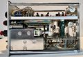
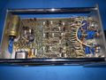
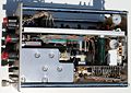
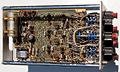
The signal path of each channel begins with the signal passing through the attenuators. | |||
Then it is clamped by two diodes and applied to the gate of a JFET source follower. | |||
The source of the source follower is the trigger pickoff point. | The source of the source follower is the trigger pickoff point. | ||
From there the vertical signal path goes through an NPN emitter follower | From there the vertical signal path goes through an NPN emitter follower, then an NPN differential amplifier, at which point the signal becomes differential. | ||
Next, the signal passes through an analog multiplexer made with [[1N4152]] silicon switching diodes. | |||
at which point the signal becomes differential. | |||
Next, the signal passes through an analog multiplexer | After the multiplexer network, the signal passes through a common base amplifier followed by [[6DJ8]] tube operating in common grid configuration. | ||
made with [[1N4152]] silicon switching diodes. | |||
After the multiplexer network, the signal passes through a common base amplifier | |||
followed by [[6DJ8]] tube operating in common grid configuration. | |||
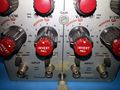
There is an "identify" switch for each channel, which when pressed shifts the trace up by ~3 mm, to aid identification of the corresponding signal/channel. | |||
of the | This is achieved by offsetting position control circuitry with a small resistance to shift position. | ||
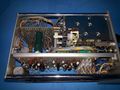
The 12.1 V and −15 V power for the plug-in is generated onboard using a step-up transformer, whose primary is connected to the 6.3 V heater supply from the mainframe and the two secondaries drive the onboard series regulators. | |||
==Pictures== | ==Pictures== | ||
<gallery> | <gallery> | ||
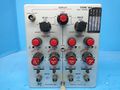
Tek_1A4_Front.jpeg | Front | |||
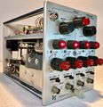
Tek 1A4_RHS.jpeg | RHS | |||
Tek_1A4_LHS.jpeg | LHS | |||
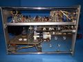
Tek_1A4_Top.jpeg | Top | |||
Tek_1A4_Bottom.jpeg | Bottom | |||
Tek 1A4_Iso.jpeg | Front/Side | |||
Tek 1a4 front n1.jpg | |||
Tek 1a4 left n1.jpg | |||
Tek 1a4 top n1.jpg | |||
Tek 1a4 right n1.jpg | |||
Tek 1a4 bottom n1.jpg | |||
Tek 1a4 rear n1.jpg | |||
Tek 1a4 frontclose n1.jpg | |||
1a4 front.jpg | |||
1a4 right2.jpg | |||
1a4 top.jpg | |||
1a4 bottom.jpg | |||
</gallery> | </gallery> | ||
==Components== | |||
{{Parts|1A4}} | |||
[[Category:500 series plugins]] | [[Category:500 series plugins]] | ||
Latest revision as of 10:23, 13 November 2023

The Tektronix Type 1A4 is a 1-series vertical plug-in for 500-series scopes. It has four input channels and 50 MHz bandwidth.
Type 1A4 was introduced in 1967 and lasted until the end of the 500-series scopes line.
The four channels are grouped into two groups of two channels. Type 1A4 has a special "trace slaving" mode which, when used in a 547 mainframe, allows channels 1 and 2 to be displayed using the A time base, and channels 3 and 4 to be displayed with the B time base. This allows high-speed and low-speed signals to be displayed together, similar to what a dual-beam scope can do, but without some of the cost and complexity.
Like the Type 1A2 and unlike the Type 1A1, the Type 1A4 has a Trigger Output selector that controls which channel provides triggering when the mainframe trigger is in Plug-In mode, for scopes having this feature (544, 546, 547, 549, 556, late 555).
Key Specifications
| Plug-in Bandwidth | DC to 50 MHz |
|---|---|
| Maximum Input Sensitivity | 10 mV/div |
| Rise time | 7 ns |
| Input Impedance | 1 MΩ // 20 pF |
| Maximum Input Voltage | 600 V combined DC and peak AC |
| Signal Output Impedence | 50 Ω |
Cascaded operation using the Signal Out jack can achieve a sensitivity of approximately 200 μV/div AC with about 20 Hz - 1 MHz bandwidth.
Internals
The signal path of each channel begins with the signal passing through the attenuators. Then it is clamped by two diodes and applied to the gate of a JFET source follower. The source of the source follower is the trigger pickoff point. From there the vertical signal path goes through an NPN emitter follower, then an NPN differential amplifier, at which point the signal becomes differential. Next, the signal passes through an analog multiplexer made with 1N4152 silicon switching diodes.
After the multiplexer network, the signal passes through a common base amplifier followed by 6DJ8 tube operating in common grid configuration.
There is an "identify" switch for each channel, which when pressed shifts the trace up by ~3 mm, to aid identification of the corresponding signal/channel. This is achieved by offsetting position control circuitry with a small resistance to shift position.
The 12.1 V and −15 V power for the plug-in is generated onboard using a step-up transformer, whose primary is connected to the 6.3 V heater supply from the mainframe and the two secondaries drive the onboard series regulators.
Pictures
-
Front
-
RHS
-
LHS
-
Top
-
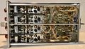
Bottom
-
Front/Side
-
-
-
-
-
-
-
-
-
-
-


Components
Some Parts Used in the 1A4
| Part | Part Number(s) | Class | Description | Used in |
|---|---|---|---|---|
| 6DJ8 | 154-0187-00 • 154-0305-00 | Vacuum Tube (Dual Triode) | dual triode | 132 • 161 • 310A • 316 • 317 • 502 • 502A • 503 • 504 • 506 • 515 • 516 • 519 • 526 • 529 • RM529 • 533 • 535 • 536 • 543 • 544 • 545 • 545A • 545B • 546 • 547 • 549 • 555 • 556 • 561A • 561S • 564 • 565 • 567 • 581 • 581A • 585 • 585A • 661 • 1A4 • 1S1 • 60 • 2A60 • 63 • 2A63 • 67 • 2B67 • 3A1 • 3A1S • 3A2 • 3A3 • 3A6 • 3A7 • 72 • 3A72 • 75 • 3A75 • 4S2 • 51 • 3B1 • 3B1S • 3B2 • 3B3 • 3B4 • 3M1 • 3S76 • 3T77 • 3T77A • 9A1 • 9A2 • 1121 • 80 • 81 • 82 • 86 • B • O • W • Z • Telequipment D56 • Telequipment S32A • Telequipment D52 • S-311 • Telequipment TD51 • Telequipment S52 • Telequipment S51 • Telequipment Type A • TU-4 |