492: Difference between revisions
No edit summary |
No edit summary |
||
| (33 intermediate revisions by 4 users not shown) | |||
| Line 1: | Line 1: | ||
{{ | {{Instrument Sidebar | ||
|class=Spectrum Analyzer | |||
summary=Spectrum Analyzer | |manufacturer=Tektronix | ||
image= Tek 492 3.jpg | | |model=492 | ||
caption=Tektronix 492 | | |summary=21 GHz Spectrum Analyzer | ||
introduced=1980 | | |image=Tek 492 3.jpg | ||
discontinued=1993 | | |caption=Tektronix 492 | ||
manuals= | |introduced=1980 | ||
|discontinued=1993 | |||
* [[Media:070-2726-03.pdf| Tektronix 492 | |designers=Larry Lockwood;Steve Morton;Linley Gumm;Robert Alm;Bob Bales;Carlos Beeck;Bill Benedict;Craig Bryant;Russell Brown;Wes Hayward;David Leatherwood;Gordon Long;Dave Morton;Bill Peterson;David Shores;Steve Skidmore;Dennis Smith;Phil Snow;Leighton Whitset;Norman Witt; | ||
* [[Media:070-3783-01.pdf| Tektronix 492 | |manuals= | ||
* [[Media:070-3784-01.pdf| Tektronix 492 | '''492/492P''' | ||
* [[Media:050-1467-01.pdf| Product modification – Variable Resolution Module Replacement | * [[Media:070-2729-00.pdf|Tektronix 492(P) Operators Handbook]] | ||
* [[Media:Tek_492_Catalog_Spec_1980.pdf| Tektronix 492 Introduction Spec ( | * [[Media:070-2726-02.pdf|Tektronix 492(P) Operator Manual -02]] (OCR) | ||
* [[Media:Tek_490-Series_Final Spec_1991.pdf| Tektronix 492 Final Spec ( | * [[Media:070-2726-03.pdf|Tektronix 492(P) Operator Manual -03]] (OCR) | ||
* [[Media:070-2727-03.pdf|Tektronix 492(P) (SN B029999 & below) Service Volume 1]] | |||
* [[Media:070-3783-01.pdf|Tektronix 492(P) Service Manual – Volume 1]] | |||
* [[Media:070-3784-01.pdf|Tektronix 492(P) Service Manual – Volume 2]] | |||
* [[Media:070-3401-00.pdf|Tektronix 492P Programmers Manual]] (OCR) | |||
'''492A/492AP/492BP''' | |||
* [[Media:070-5562-01.pdf|Tektronix 492A(P) Operators Manual -01]] | |||
* [[Media:070-5562-00.pdf|Tektronix 492A(P) Operators Manual -00]] | |||
* [[Media:070-5566-01.pdf|Tektronix 492A(P) Service Manual Vol.2]] | |||
* [[Media:070-5564-01.pdf|Tektronix 492AP/492BP Programmers Manual]] | |||
'''Modifications''' | |||
* [[Media:050-1467-01.pdf|Product modification – Variable Resolution Module Replacement]] | |||
'''Specifications''' | |||
* [[Media:Tek_492_Catalog_Spec_1980.pdf|Tektronix 492 Introduction Spec]] (OCR) | |||
* [[Media:Tek_490-Series_Final Spec_1991.pdf| Tektronix 492 Final Spec]] (OCR) | |||
}} | }} | ||
The '''Tektronix 492''' is a spectrum analyzer with a frequency range of 10 kHz to 21 GHz in coax, and up to 325 GHz with external waveguide mixers (492PGM N/A). The '''P''' suffix designation indicates GPIB '''P'''rogrammability. | |||
During the lifespan of the instrument, the specifications and included options were altered several times. A major upgrade was the introduction of the '''492A''' in 1987 which added marker functionality and resolution bandwidths and the '''492BP''' in 1989 which added a counter and increased the displayed dynamic range. The '''492PGM''' is a cost reduced version introduced in 1990. Also see [[49X Series Comparison]]. | |||
Regarding the 492, [[Linley Gumm]] says, | |||
<blockquote> | |||
Given how complicated it was, many people contributed to the design. I currently have a list of 20 people. | |||
The problem is that I’m sure that I am missing several people and I hate to submit a list without them. | |||
The | The 492 was designed at the request of the military. They asked for a modern replacement of the [[491]]. | ||
It was required that it provide coaxial input coverage of the lower microwave bands (~18 GHz), | |||
be very rugged, be a one person carry and fit through a submarine hatch. | |||
There was a lot more than that of course. | |||
When the 492 program started I was the project leader of the [[7L18]] and was still working to finish it off. | |||
The 7L18 was the first instrument at Tektronix to use a microprocessor. | |||
We had worked long and hard to learn how to electronically switch and control all the elements that were controlled by physical switch closures in the earlier instruments. | |||
Understand that to position the frequency of a YIG filter correctly with respect to the frequency of a YIG oscillator | |||
one must generate very quiet DC voltages accurate to roughly 1 part in 20,000 (i.e. 1 MHz in 18 GHz), so new control techniques were required. | |||
Plus the TEK-made YIG filter designed for the 7L18 was therefore ready for use in the 492. | |||
We had also learned quite a number of things not to do and this was also used to anchor the 492 program. | |||
I say this to note that most of the long lasting, “classic”, Tektronix products were often the second, but more often the third generation product by the same design group. | |||
The 492 was definitely a second generation product in its use of microwave components and a microprocessor based control system; | |||
perhaps a third if you lump the [[7L12]], [[7L13]] (microwave systems) and the [[7L5]] (electronic bus control system) together as a first generation. | |||
[[Larry Lockwood]] led the first part of the program. He defined the RF and microwave frequency conversion architecture of the 492. | |||
As the program progressed, [[Steve Morton]] became the project manager of the initial 492 program. | |||
Recognize that beyond that initial project, follow-on design work went on for years as new features were added. | |||
Further, after their initial design work in the initial portion of the project, designers often went on to do rather different subsystems in the follow-ons. | |||
I worked on the 492 as a circuit designer in the initial design and in several other roles later, none of which were leadership roles. | |||
The other people I can recall having worked on the 492 at some point in its life were: | |||
[[Robert Alm]], | |||
[[Bob Bales]], | |||
[[Carlos Beeck]], | |||
[[Bill Benedict]], | |||
[[Craig Bryant]], | |||
[[Russell Brown]], | |||
[[Wes Hayward]], | |||
[[David Leatherwood]], | |||
[[Gordon Long]], | |||
[[Dave Morton]], | |||
[[Bill Peterson]], | |||
[[David Shores]], | |||
[[Steve Skidmore]], | |||
[[Dennis Smith]], | |||
[[Phil Snow]], | |||
[[Leighton Whitset]], and | |||
[[Norman Witt]]. | |||
Be aware my spelling is often “inventive”. There are at least two other names I can’t bring to mind. | |||
</blockquote> | |||
{{BeginSpecs}} | {{BeginSpecs}} | ||
{{Spec | Frequency | {{Spec | Frequency | | ||
* Coaxial Input Bands: 10 kHz to 21 GHz | * Coaxial Input Bands: 10 kHz to 21 GHz | ||
* External Waveguide mixers: 10 kHz to 325 GHz (applies to 492BP not 492PGM) }} | * External Waveguide mixers: 10 kHz to 325 GHz (applies to 492BP not 492PGM) }} | ||
{{Spec | Frequency Span | {{Spec | Frequency Span | 492BP: 100 Hz/div to 10 GHz/div; 492PGM: 200 MHz to 1 GHz; both in 1, 2, 5 sequence; plus 0 Hz and MAX }} | ||
{{Spec | Resolution Bandwidth | {{Spec | Resolution Bandwidth (-6 dB bandwidth) | 492BP: 100 Hz to 3 MHz; 492PGM: 1 kHz to 3 MHz; both in decade steps }} | ||
{{Spec | RF Input | {{Spec | RF Input | 50 Ω, max. +30 dBm (1 W) CW; / 75 W peak pulse (1 µs, 0.1% duty factor) }} | ||
{{Spec | RF Attenuator | 0 dB to 60 dB, 10 dB steps }} | |||
{{Spec | RF Attenuator | {{Spec | Reference Level | -117 dBm to +30 dBm }} | ||
{{Spec | Reference Level | {{Spec | Sweep Speed | 10 sec/div to 20 µs/div, 1−2−5 }} | ||
{{Spec | Sweep Speed | {{Spec | Video Bandwidth | 492BP: 0.3 Hz to 30 kHz; 492PGM: 3 Hz to 30 kHz }} | ||
{{Spec | Video Bandwidth | {{Spec | Memory | NVRAM for up to 9 waveform displays, up to 10 front panel setups, plus 8 K for programming macros | ||
}} | |||
{{Spec | Triggering Modes | Free Run, Line, Video, Single, External }} | {{Spec | Triggering Modes | Free Run, Line, Video, Single, External }} | ||
{{Spec | | {{Spec | Displayed Average Noise | −30 dBm to −131 dBm }} | ||
{{Spec | Display Dynamic Range | 492BP: 90 dB; 492PGM: 80 dB }} | {{Spec | Display Dynamic Range | 492BP: 90 dB; 492PGM: 80 dB }} | ||
{{Spec | Calibrator (Cal out) | | {{Spec | Calibrator (Cal out) | 50 Ω, -20 dBm ±0.3 dB at 100 MHz }} | ||
{{Spec | Weight | 492BP: 21.8 kg (47 lbs) 492PGM: 21.3 kg (46 lbs) }} | |||
{{Spec | Weight | 492BP: 21. | |||
{{Spec | Power | 90 − 132 V<sub>AC</sub>, 48 to 440 Hz; 180 – 250 V<sub>AC</sub>, 48 to 440 Hz. At 115 V<sub>AC</sub>, 60 Hz, 210 W max }} | {{Spec | Power | 90 − 132 V<sub>AC</sub>, 48 to 440 Hz; 180 – 250 V<sub>AC</sub>, 48 to 440 Hz. At 115 V<sub>AC</sub>, 60 Hz, 210 W max }} | ||
{{EndSpecs}} | {{EndSpecs}} | ||
==Options== | ==Options== | ||
* Opt. 02: | * Opt. 01: Internal Preselection. (Limits the first band to 1.8 GHz instead 4.2 GHz). Later became standard | ||
* Opt. 07: | * Opt. 02: Digital Storage. Later became standard | ||
* Opt. 03: Frequency Stabilization & 100 Hz Resolution. Later became standard | |||
* Opt. 07: 75 Ω dBmV input and calibration in addition to the normal 50 Ω dBm input and calibration. (Not combinable with Opt. 21 and 22; no external mixer capability). Include 42-inch 75 Ω BNC-BNC coax cable and BNC male to “F” female adapter. | |||
* Opt. 21: (492BP) High performance 18 to 40 GHz WM490 Series Waveguide Mixer Set | * Opt. 21: (492BP) High performance 18 to 40 GHz WM490 Series Waveguide Mixer Set | ||
* Opt. 22: (492BP) Same as Opt. 21 plus WM490U (40-60 GHz) Waveguide Mixer | * Opt. 22: (492BP) Same as Opt. 21 plus WM490U (40-60 GHz) Waveguide Mixer | ||
| Line 72: | Line 132: | ||
* [https://www.circuitben.net/node/4 Tek 492 DIY USB interface project] | * [https://www.circuitben.net/node/4 Tek 492 DIY USB interface project] | ||
* [[016-0631-01|Waveguide Mixers for 492 and 7L18]] | * [[016-0631-01|Waveguide Mixers for 492 and 7L18]] | ||
* [https://www.youtube.com/watch?v=tKC24SpHTSY YouTube: Tektronix 492 and 496 Portable Spectrum Analyzers] | |||
* [[067-1137-99|067-1137-99 GPIB to accessory controller]] | |||
{{Documents|Link=492}} | |||
==Connections== | |||
Front panel inputs/outputs are: | |||
* RF INPUT (50 Ω [[N connector]]) – Input for RF signals to 21 GHz. If input signal has a DC component, use a blocking capacitor | |||
* CAL OUT ([[BNC connector]]) – Provides 100 MHz, –20 dBm signal and a comb of frequency markers 100 MHz apart | |||
* 1ST LO OUTPUT ([[SMA connector]]) – Output of the 1st local oscillator, must be terminated into 50 Ω when not connected. | |||
* 2ND LO OUTPUT ([[SMA connector]]) – Output of the 2nd local oscillator, must be terminated into 50 Ω when not connected. | |||
* EXTERNAL MIXER RF INPUT ([[TNC connector]], 50 Ω) | |||
* Camera Power | |||
Rear panel inputs/outputs are: | |||
* PROBE POWER – Provides operating voltages (+5 V, -15 V, +15 V; 100 mA max each) for active probes | |||
* HORIZ/TRIG (input, [[BNC connector|BNC]]) – In External Triggering mode, AC coupled input for trigger signals; when TIME/DIV selection is EXT, DC coupled input for horizontal sweep voltages | |||
* MARKER/VIDEO (B053575+, output, [[BNC connector|BNC]]) – interfaces the 492/492P with a TV Sideband Adapter, such as the Tek [[1405]], so a marker from the adapter is displayed on the internal video. External video applied to this connector will also be displayed if pin 1 of the ACCESSORIES connector is grounded. | |||
** Opt. 42 replaces MARKER/VIDEO with 110 MHz IF (output, [[BNC connector|BNC]]) – 3 dB signal bandwidth ≥ 4.5 MHz | |||
* EXT PRESELECTOR (B053574 and below) (output, [[BNC connector|BNC]]) – variable voltage (approx -0.2 V to +10 V) proportional to center frequency, for preselector bands of Opt. 01 instruments, to drive an external preselector | |||
* HORIZ (output, [[BNC connector|BNC]]) – 0.5 V/div horizontal signal | |||
* VERT (output, [[BNC connector|BNC]]) – Video signal with 0.5 V/Div | |||
* PEN LIFT (output, [[BNC connector|BNC]]) – TTL compatible signal to lift the pen of a chart recorder during sweep retrace. In Opt. 42 instruments this port may also be used for inputting external video if pin 1 of the ACCESSORY connector is grounded. | |||
* 10 MHz IF (output, [[BNC connector|BNC]]) – Output of the 10 MHz IF | |||
* J104 ACCESSORY (B053575+ only), female [[DB25 connector]] – Provides bidirectional access to the instrument bus. | |||
* IEEE STD 488 PORT [[GPIB interface]] – Added to all "P" suffixed instruments | |||
==Pictures== | ==Pictures== | ||
===492=== | |||
<gallery> | |||
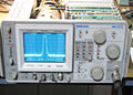
Tek 492 trace open.jpg | |||
Tek 492 top internal.jpg|Internal top view | |||
</gallery> | |||
===492A=== | |||
<gallery> | <gallery> | ||
Tek 492 3.jpg | Tek 492 3.jpg | ||
| Line 82: | Line 175: | ||
Tek 492 7.jpg | Tek 492 7.jpg | ||
Tek 492 8.jpg | Tek 492 8.jpg | ||
</gallery> | |||
===492BP=== | |||
<gallery> | |||
492BP_ebay_1.jpg | |||
492BP_ebay_2.jpg | |||
492BP_ebay_3.jpg | |||
492BP_ebay_4.jpg | |||
492BP_ebay_5.jpg | |||
</gallery> | |||
===492PGM=== | |||
<gallery> | |||
492PGM_front.jpg | |||
</gallery> | |||
[[Category: Spectrum | [[Category:Spectrum analyzers]] | ||
[[Category:Manual needed]] | |||
Latest revision as of 06:05, 20 March 2024

The Tektronix 492 is a spectrum analyzer with a frequency range of 10 kHz to 21 GHz in coax, and up to 325 GHz with external waveguide mixers (492PGM N/A). The P suffix designation indicates GPIB Programmability.
During the lifespan of the instrument, the specifications and included options were altered several times. A major upgrade was the introduction of the 492A in 1987 which added marker functionality and resolution bandwidths and the 492BP in 1989 which added a counter and increased the displayed dynamic range. The 492PGM is a cost reduced version introduced in 1990. Also see 49X Series Comparison.
Regarding the 492, Linley Gumm says,
Given how complicated it was, many people contributed to the design. I currently have a list of 20 people. The problem is that I’m sure that I am missing several people and I hate to submit a list without them.
The 492 was designed at the request of the military. They asked for a modern replacement of the 491. It was required that it provide coaxial input coverage of the lower microwave bands (~18 GHz), be very rugged, be a one person carry and fit through a submarine hatch. There was a lot more than that of course.
When the 492 program started I was the project leader of the 7L18 and was still working to finish it off. The 7L18 was the first instrument at Tektronix to use a microprocessor. We had worked long and hard to learn how to electronically switch and control all the elements that were controlled by physical switch closures in the earlier instruments.
Understand that to position the frequency of a YIG filter correctly with respect to the frequency of a YIG oscillator one must generate very quiet DC voltages accurate to roughly 1 part in 20,000 (i.e. 1 MHz in 18 GHz), so new control techniques were required. Plus the TEK-made YIG filter designed for the 7L18 was therefore ready for use in the 492.
We had also learned quite a number of things not to do and this was also used to anchor the 492 program. I say this to note that most of the long lasting, “classic”, Tektronix products were often the second, but more often the third generation product by the same design group. The 492 was definitely a second generation product in its use of microwave components and a microprocessor based control system; perhaps a third if you lump the 7L12, 7L13 (microwave systems) and the 7L5 (electronic bus control system) together as a first generation.
Larry Lockwood led the first part of the program. He defined the RF and microwave frequency conversion architecture of the 492. As the program progressed, Steve Morton became the project manager of the initial 492 program. Recognize that beyond that initial project, follow-on design work went on for years as new features were added. Further, after their initial design work in the initial portion of the project, designers often went on to do rather different subsystems in the follow-ons.
I worked on the 492 as a circuit designer in the initial design and in several other roles later, none of which were leadership roles.
The other people I can recall having worked on the 492 at some point in its life were: Robert Alm, Bob Bales, Carlos Beeck, Bill Benedict, Craig Bryant, Russell Brown, Wes Hayward, David Leatherwood, Gordon Long, Dave Morton, Bill Peterson, David Shores, Steve Skidmore, Dennis Smith, Phil Snow, Leighton Whitset, and Norman Witt.
Be aware my spelling is often “inventive”. There are at least two other names I can’t bring to mind.
Key Specifications
| Frequency |
|
|---|---|
| Frequency Span | 492BP: 100 Hz/div to 10 GHz/div; 492PGM: 200 MHz to 1 GHz; both in 1, 2, 5 sequence; plus 0 Hz and MAX |
| Resolution Bandwidth (-6 dB bandwidth) | 492BP: 100 Hz to 3 MHz; 492PGM: 1 kHz to 3 MHz; both in decade steps |
| RF Input | 50 Ω, max. +30 dBm (1 W) CW; / 75 W peak pulse (1 µs, 0.1% duty factor) |
| RF Attenuator | 0 dB to 60 dB, 10 dB steps |
| Reference Level | -117 dBm to +30 dBm |
| Sweep Speed | 10 sec/div to 20 µs/div, 1−2−5 |
| Video Bandwidth | 492BP: 0.3 Hz to 30 kHz; 492PGM: 3 Hz to 30 kHz |
| Memory | NVRAM for up to 9 waveform displays, up to 10 front panel setups, plus 8 K for programming macros |
| Triggering Modes | Free Run, Line, Video, Single, External |
| Displayed Average Noise | −30 dBm to −131 dBm |
| Display Dynamic Range | 492BP: 90 dB; 492PGM: 80 dB |
| Calibrator (Cal out) | 50 Ω, -20 dBm ±0.3 dB at 100 MHz |
| Weight | 492BP: 21.8 kg (47 lbs) 492PGM: 21.3 kg (46 lbs) |
| Power | 90 − 132 VAC, 48 to 440 Hz; 180 – 250 VAC, 48 to 440 Hz. At 115 VAC, 60 Hz, 210 W max |
Options
- Opt. 01: Internal Preselection. (Limits the first band to 1.8 GHz instead 4.2 GHz). Later became standard
- Opt. 02: Digital Storage. Later became standard
- Opt. 03: Frequency Stabilization & 100 Hz Resolution. Later became standard
- Opt. 07: 75 Ω dBmV input and calibration in addition to the normal 50 Ω dBm input and calibration. (Not combinable with Opt. 21 and 22; no external mixer capability). Include 42-inch 75 Ω BNC-BNC coax cable and BNC male to “F” female adapter.
- Opt. 21: (492BP) High performance 18 to 40 GHz WM490 Series Waveguide Mixer Set
- Opt. 22: (492BP) Same as Opt. 21 plus WM490U (40-60 GHz) Waveguide Mixer
- Opt. 23: GRASP software, PC2A interface, and GPIB cable
- Opt. 27: Epson LT-386SX, GRASP software, PC2A interface, and GPIB cable
- Opt. 28: Compaq Deskpro 386S, Model 40, GRASP software, PC2A interface, and GPIB cable
- Opt. 39: Non-lithium (Silver) batteries for battery-backed memory
- Opt. 41: Digital Microwave Radio Measurement Enhancement package
- Opt. 42: Replaces MARKER/VIDEO input port on the rear panel with a 110 MHz IF output port that provides a 3 dB signal bandwidth ≥ 4.5 MHz
- Opt. 45: (all except 492PGM) MATE/CIIL language interface
Links
- Comparison of 492 with 494 and 7L18
- 49x Service notes @ John Miles KE5FX
- KE5FX GPIB toolkit
- ROM replacement
- Tek 492 DIY USB interface project
- Waveguide Mixers for 492 and 7L18
- YouTube: Tektronix 492 and 496 Portable Spectrum Analyzers
- 067-1137-99 GPIB to accessory controller
Documents Referencing 492
| Document | Class | Title | Authors | Year | Links |
|---|---|---|---|---|---|
| Tekscope 1980 V12 N1.pdf | Article | Packaging A Spectrum Analyzer for Performance, Maintainability and Survival | Carlos Beeck | 1980 | 492 |
| Tekscope 1980 V12 N1.pdf | Article | A First Converter With Field Replaceable Diodes | Phil Snow | 1980 | 492 |
| Tekscope 1980 V12 N1.pdf | Article | A Switching Power Supply For The 492 Spectrum Analyzer | David Leatherwoood | 1980 | 492 |
| Tekscope 1980 V12 N1.pdf | Article | A Portable High-Performance Microwave Spectrum Analyzer | Dave Morton | 1980 | 492 |
| Tekscope 1980 V12 N1.pdf | Article | The Tektronix 492 Is A New-Generation Spectrum Analyzer | Morris Engelson | 1980 | 492 |
| Tekscope 1980 V12 N1.pdf | Article | Making Measurements with the 492 | Morris Engelson | 1980 | 492 |
Connections
Front panel inputs/outputs are:
- RF INPUT (50 Ω N connector) – Input for RF signals to 21 GHz. If input signal has a DC component, use a blocking capacitor
- CAL OUT (BNC connector) – Provides 100 MHz, –20 dBm signal and a comb of frequency markers 100 MHz apart
- 1ST LO OUTPUT (SMA connector) – Output of the 1st local oscillator, must be terminated into 50 Ω when not connected.
- 2ND LO OUTPUT (SMA connector) – Output of the 2nd local oscillator, must be terminated into 50 Ω when not connected.
- EXTERNAL MIXER RF INPUT (TNC connector, 50 Ω)
- Camera Power
Rear panel inputs/outputs are:
- PROBE POWER – Provides operating voltages (+5 V, -15 V, +15 V; 100 mA max each) for active probes
- HORIZ/TRIG (input, BNC) – In External Triggering mode, AC coupled input for trigger signals; when TIME/DIV selection is EXT, DC coupled input for horizontal sweep voltages
- MARKER/VIDEO (B053575+, output, BNC) – interfaces the 492/492P with a TV Sideband Adapter, such as the Tek 1405, so a marker from the adapter is displayed on the internal video. External video applied to this connector will also be displayed if pin 1 of the ACCESSORIES connector is grounded.
- Opt. 42 replaces MARKER/VIDEO with 110 MHz IF (output, BNC) – 3 dB signal bandwidth ≥ 4.5 MHz
- EXT PRESELECTOR (B053574 and below) (output, BNC) – variable voltage (approx -0.2 V to +10 V) proportional to center frequency, for preselector bands of Opt. 01 instruments, to drive an external preselector
- HORIZ (output, BNC) – 0.5 V/div horizontal signal
- VERT (output, BNC) – Video signal with 0.5 V/Div
- PEN LIFT (output, BNC) – TTL compatible signal to lift the pen of a chart recorder during sweep retrace. In Opt. 42 instruments this port may also be used for inputting external video if pin 1 of the ACCESSORY connector is grounded.
- 10 MHz IF (output, BNC) – Output of the 10 MHz IF
- J104 ACCESSORY (B053575+ only), female DB25 connector – Provides bidirectional access to the instrument bus.
- IEEE STD 488 PORT GPIB interface – Added to all "P" suffixed instruments
Pictures
492
-
-
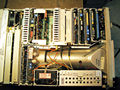
Internal top view


