Deflection blanking: Difference between revisions
Jump to navigation
Jump to search
No edit summary |
(Schematic reference) |
||
| (4 intermediate revisions by one other user not shown) | |||
| Line 6: | Line 6: | ||
The latter approach is called '''deflection blanking'''. | The latter approach is called '''deflection blanking'''. | ||
Deflection blanking is used in several Tektronix instruments, | Deflection blanking is used in several Tektronix instruments, | ||
including the [[211]], [[212]], [[213]], [[214]], [[221]], [[321]], [[323]], [[326]], [[422]], [[503]], [[504]], [[506]], [[527]], [[560]], [[561]], [[564]], [[565]], [[567]], and [[661]]. | including the [[211]], [[212]], [[213]], [[214]], [[221]], [[305]], [[321]], [[323]], [[326]], [[422]], [[503]], [[504]], [[506]], [[527]], [[528]], [[529]], [[560]], [[561]], [[564]], [[565]], [[567]], [[568]], and [[661]]. | ||
<gallery> | |||
Tek_545_Blanking.png | Tek 545 blanking signal is applied to CRT grid. | |||
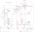
Tek_422-Blanking.png | Tek 422 deflection blanking. | |||
</gallery> | |||
[[Category:Circuits and Concepts]] | [[Category:Circuits and Concepts]] | ||
Latest revision as of 11:00, 12 June 2020
Oscilloscopes have two main ways to avoid drawing on the screen between traces.
One is to turn off the CRT beam by making the CRT grid negative (e.g., −150 V) relative to the CRT cathode.
Another way is to leave the CRT beam on, but to deflect it away from the CRT phosphor. The latter approach is called deflection blanking. Deflection blanking is used in several Tektronix instruments, including the 211, 212, 213, 214, 221, 305, 321, 323, 326, 422, 503, 504, 506, 527, 528, 529, 560, 561, 564, 565, 567, 568, and 661.
-
Tek 545 blanking signal is applied to CRT grid.
-

Tek 422 deflection blanking.

