S-52: Difference between revisions
(links, better pics) |
No edit summary |
||
| (6 intermediate revisions by one other user not shown) | |||
| Line 1: | Line 1: | ||
{{Plugin Sidebar | | {{Plugin Sidebar 2| | ||
title=Tektronix S-52 | | title=Tektronix S-52 | | ||
summary=Pulse Generator | | summary=Pulse Generator | | ||
image=Tek-s52-front.jpg | | image=Tek-s52-front.jpg | | ||
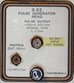
caption=S-52 head, front panel | | caption=S-52 head, front panel | | ||
series=[[ | series=[[3S2]], [[7S11]], [[7S12]] Sampling Plugins | | ||
introduced=1971 | | |||
discontinued=1990 | | |||
manuals= | manuals= | ||
* [http://w140.com/Tek_S-52_Manual.pdf Tektronix S-52 Manual (PDF)] | * [http://w140.com/Tek_S-52_Manual.pdf Tektronix S-52 Manual (PDF)] | ||
| Line 15: | Line 16: | ||
It puts out a 200 mV pulse into a load of 50 Ω. The pulse has a rise time of 25 ps or less. | It puts out a 200 mV pulse into a load of 50 Ω. The pulse has a rise time of 25 ps or less. | ||
The output is an [[ | The output is an [[SMA connector]]. | ||
In addition to the main pulse output, the S-52 also produces a pre-trigger pulse 85 ns before the main pulse. | In addition to the main pulse output, the S-52 also produces a pre-trigger pulse 85 ns before the main pulse. | ||
The delay is generated with a digital counter, and jitter between the pre-trigger pulse and the main pulse is specified as less than 10 ps. The pre-trigger pulse uses a [[ | The delay is generated with a digital counter, | ||
and jitter between the pre-trigger pulse and the main pulse is specified as less than 10 ps. | |||
The pre-trigger pulse uses a [[BSM connector]]. | |||
{{BeginSpecs}} | {{BeginSpecs}} | ||
| Line 33: | Line 29: | ||
{{Spec | Pre-trigger output | 85 ns before main pulse (jitter < 10 ps), +1 V into 50 Ω (BSM) }} | {{Spec | Pre-trigger output | 85 ns before main pulse (jitter < 10 ps), +1 V into 50 Ω (BSM) }} | ||
{{EndSpecs}} | {{EndSpecs}} | ||
==Internals== | |||
The S-52 generates the main output pulse using a 50 mA low-capacitance [[tunnel diodes|tunnel diode]] with part number [[153-0400-00]]. | |||
The S-52 is [[S-50#Comparison_of_S-50_and_S-52|similar to the S-50]], | |||
but the S-50 has twice the pulse amplitude. | |||
The reason for this is that the S-52 has a 48 Ω resistor between the output tunnel diode | |||
and the output connector providing back termination, while the S-50 has no such resistor. | |||
Although the S-52 produces a smaller pulse, its output impedance is much better controlled than that of the S-50, | |||
and the output resistor may also provide some limited protection for the output tunnel diode. | |||
==Links== | ==Links== | ||
* [http://www.amplifier.cd/Test_Equipment/Tektronix/Tektronix_7000_series_special/S-52.html Tek S-52 page @ amplifier.cd] | * [http://www.amplifier.cd/Test_Equipment/Tektronix/Tektronix_7000_series_special/S-52.html Tek S-52 page @ amplifier.cd] | ||
* http://www.barrytech.com/tektronix/tek7000/teks52.html | * [http://www.barrytech.com/tektronix/tek7000/teks52.html Tektronix S-52 @ barrytech.com] | ||
==Pictures== | ==Pictures== | ||
<gallery> | <gallery> | ||
Tek-s52-front.jpg | S-52 front | |||
7s12-s6-s52-f.jpg | S-52 pulse generator and [[S-6|S-6 sampling head]] in a [[7S12|7S12 TDR/Sampler plugin]] | |||
</gallery> | </gallery> | ||
===Internal=== | ===Internal=== | ||
<gallery> | <gallery> | ||
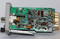
Tek-s52-1.jpg | A1 Timing board (right) | |||
Tek-s52-2.jpg | A3 Trigger board (left) | |||
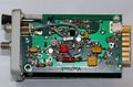
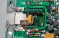
Tek-s52-3.jpg | A2 Tunnel Diode Control board (center) | |||
Tek-s52-4.jpg | Tunnel diode mount | |||
Tek-s52-diode-mount.jpg | Tunnel diode mount, detail | |||
Tek_s-52_schem2.png |Schematic | |||
</gallery> | </gallery> | ||
===Measurements=== | ===Measurements=== | ||
<gallery> | <gallery> | ||
7s12-self-portrait.jpg | TDR "Self Portrait" — pulse reflected on S-6 "through" path (approx. 120 ps one way) | |||
7s12-s52-incident.jpg | 7S12 displaying the incident pulse from an S-52 (nom. < 25 ps) through an S-6 head (nom. < 30 ps). Displayed rise time ~35 ps confirms spec. | |||
7s12-s52-pulse-1.jpg | Full pulse pattern of a 7S12/S-52 in real time (top trace) and sampled (bottom trace) shown simultaneously on [[7844]]. 7S12 trace at slowest possible sweep. | |||
7s12-s52-pulse-2.jpg | S-52 pulse in real time (top trace) and sampled (bottom trace) shown simultaneously on [[7844]]. Approximately equal time scales. | |||
</gallery> | </gallery> | ||
[[Category:7000 and 3S series sampling heads]] | [[Category:7000 and 3S series sampling heads]] | ||
Revision as of 17:55, 3 February 2018
The Tektronix S-52 is a pulse generator head compatible with S-series sampling units like the 3S2, 7S11, and 7S12.
It puts out a 200 mV pulse into a load of 50 Ω. The pulse has a rise time of 25 ps or less. The output is an SMA connector.
In addition to the main pulse output, the S-52 also produces a pre-trigger pulse 85 ns before the main pulse. The delay is generated with a digital counter, and jitter between the pre-trigger pulse and the main pulse is specified as less than 10 ps. The pre-trigger pulse uses a BSM connector.
Key Specifications
| Rise time | < 25 ps |
|---|---|
| Output amplitude | 200 mV into 50 Ω (SMA) |
| Output impedance | 50 Ω «reverse terminated» (i.e. having controlled source impedance) |
| Pre-trigger output | 85 ns before main pulse (jitter < 10 ps), +1 V into 50 Ω (BSM) |
Internals
The S-52 generates the main output pulse using a 50 mA low-capacitance tunnel diode with part number 153-0400-00.
The S-52 is similar to the S-50, but the S-50 has twice the pulse amplitude. The reason for this is that the S-52 has a 48 Ω resistor between the output tunnel diode and the output connector providing back termination, while the S-50 has no such resistor. Although the S-52 produces a smaller pulse, its output impedance is much better controlled than that of the S-50, and the output resistor may also provide some limited protection for the output tunnel diode.
Links
Pictures
-
S-52 front
-
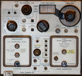
S-52 pulse generator and S-6 sampling head in a 7S12 TDR/Sampler plugin


Internal
-
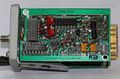
A1 Timing board (right)
-
A3 Trigger board (left)
-
A2 Tunnel Diode Control board (center)
-
Tunnel diode mount
-
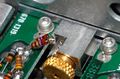
Tunnel diode mount, detail
-
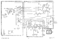
Schematic


Measurements
-
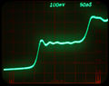
TDR "Self Portrait" — pulse reflected on S-6 "through" path (approx. 120 ps one way)
-
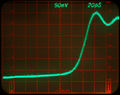
7S12 displaying the incident pulse from an S-52 (nom. < 25 ps) through an S-6 head (nom. < 30 ps). Displayed rise time ~35 ps confirms spec.
-
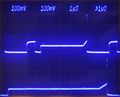
Full pulse pattern of a 7S12/S-52 in real time (top trace) and sampled (bottom trace) shown simultaneously on 7844. 7S12 trace at slowest possible sweep.
-
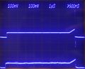
S-52 pulse in real time (top trace) and sampled (bottom trace) shown simultaneously on 7844. Approximately equal time scales.


