SG503: Difference between revisions
Jaredcabot (talk | contribs) (Added service notes) |
No edit summary |
||
| (18 intermediate revisions by 5 users not shown) | |||
| Line 1: | Line 1: | ||
{{TM500 | mfg=Tektronix | type=SG503 | function=250 MHz leveled sinewave generator | class=signal generator | image= | {{TM500 | mfg=Tektronix | type=SG503 | function=250 MHz leveled sinewave generator | class=signal generator | image=SG503 Front Early.jpg | introduced=1974 | discontinued=1993 | | ||
designers= |manuals= | designers= |manuals= | ||
* [[Media:070-1622-01.pdf| | * [[Media:070-1622-01-1974.pdf|SG503 Instruction Manual 070-1622-01 <br> Early type]] | ||
* [[Media:070-1622-01.pdf| | * [[Media:070-1622-01.pdf|SG503 Manual 070-1622-01 <br> s/n: B010100 through B089999]] | ||
* [[Media:070-6770-00.pdf| | * [[Media:070-6770-00.pdf|SG503 Manual 070-6770-00 <br> s/n: B090000 and up]] | ||
* [[Media:Tek SG503 Wizard Workshop mods.pdf|SG503 Modifications from Wizards Workshop]] | |||
}} | }} | ||
Nine overlapping ranges cover the frequency band from 250 kHz to 250 MHz, with an additional range reserved for a 50 kHz reference frequency. | |||
It was primarily intended to be used as an oscilloscope calibration device for measuring bandwidths up to 250 MHz. Unlike later instruments like the [[SG504]], it does not use a leveling head but was designed and calibrated with high quality coaxial cable (P/N [[012-0482-00]]) to operate as a closely matched system when terminated into a 50 Ω load. | |||
The SG503 shows the selected frequency on a 3-digit LED counter. | The SG503 shows the selected frequency on a 3-digit LED counter. | ||
| Line 13: | Line 14: | ||
{{BeginSpecs}} | {{BeginSpecs}} | ||
{{Spec | Frequency | 50 kHz, 250 kHz to 250 MHz in nine ranges }} | {{Spec | Frequency | 50 kHz, 250 kHz to 250 MHz in nine ranges }} | ||
{{Spec | Frequency accuracy | Within ±0.7 | {{Spec | Frequency accuracy | Within ±0.7 of one count of the least significant displayed digit for the indicated frequency }} | ||
{{Spec | Amplitude | 5 mV<sub>p-p</sub> to 5.5 V<sub>p-p</sub> in three decade ranges (terminated into a 50 Ω load) }} | {{Spec | Amplitude | 5 mV<sub>p-p</sub> to 5.5 V<sub>p-p</sub> in three decade ranges (terminated into a 50 Ω load) }} | ||
{{Spec | Harmonics | 2<sup>nd</sup> harmonic ≥35 dB down from fundamental, 3<sup>rd</sup> and higher harmonics ≥40 dB down }} | {{Spec | Harmonics | 2<sup>nd</sup> harmonic ≥35 dB down from fundamental, 3<sup>rd</sup> and higher harmonics ≥40 dB down }} | ||
| Line 24: | Line 25: | ||
The SG503 uses two LC Hartley oscillators, one for 100 MHz and above with an air-core inductor, the other for the lower ranges using switched ferrite-core inductors. Tuning is accomplished via a traditional three-section variable capacitor. After filtering, a regulated power amplifier stage (caution: [[beryllium oxide]] in transistor cases!) is followed by a peak-to-peak detector for the amplitude control loop, and switchable output attenuators. | The SG503 uses two LC Hartley oscillators, one for 100 MHz and above with an air-core inductor, the other for the lower ranges using switched ferrite-core inductors. Tuning is accomplished via a traditional three-section variable capacitor. After filtering, a regulated power amplifier stage (caution: [[beryllium oxide]] in transistor cases!) is followed by a peak-to-peak detector for the amplitude control loop, and switchable output attenuators. | ||
The frequency counter | The frequency counter circuit starts with a ÷8 prescaler (SP1670 and 10131 ECL flip-flops) followed by 7490 TTL BCD counters and 7-segment decoders (display not multiplexed). | ||
==Notes== | ==Notes== | ||
The Tek 012-0482-00 cable is made from RG-223 50 Ω double-braid shielded coaxial cable (or equivalent), and is exactly 36" from end-to-end. | The Tek [[012-0482-00]] cable is made from RG-223 50 Ω double-braid shielded coaxial cable (or equivalent), and is exactly 36" from end-to-end. | ||
== | ==Links== | ||
* | * [https://www.amplifier.cd/Test_Equipment/Tektronix/Tektronix_500/SG503.htm SG503 @ amplifier.cd] (German) including measurements of cable influence (1 m Belden H-155 as replacement for original cable) | ||
* [[Media:SG503_P2P_Substitute_REVISED.pdf|SG503 Peak-to-Peak detector substitute]] by John K. Bennett AE0AM | |||
* [https://www.youtube.com/watch?v=oRUtsDIOA40 SG503 Lab Check In and Calibration] by Zenwizard Studios @ YouTube | |||
* [https://www.youtube.com/watch?v=O0E6QeX82LY Tektronix SG503 Refresh and Alignments] by Zenwizard Studios @ YouTube | |||
{{Documents|Link=SG503}} | |||
* | |||
* | |||
* | |||
== | ==Prices== | ||
{| class="wikitable sortable" | |||
|- | |||
! Year | |||
! 1979 | |||
! 1980 | |||
|- | |||
! Catalog Price | |||
| align="right" | $1,325 | |||
| align="right" | $1,375 | |||
|- | |||
! In 2023 Dollars | |||
| align="right" | $5,600 | |||
| align="right" | $5,100 | |||
|} | |||
According to an [[Media:Tek Schottky Diodes Memo rot.pdf|internal memo]], annual sales were estimated at 1200 units in 1979. | |||
==Pictures== | ==Pictures== | ||
'''Early model''' | |||
<gallery> | |||
Tek SG503 early front.jpg | | |||
SG503_Front_Early.jpg | | |||
Tek SG503 early left.jpg | Left Internal | |||
Tek SG503 early right.jpg | Right Internal | |||
Tek SG503 Attenuator Board.jpg | Attenuator Board Part | |||
Tek SG503 Attenuator Board Top.jpg | Attenuator Board Top | |||
Early SG503 Attenuator Board Bottom.jpg | Attenuator Board Bottom | |||
</gallery> | |||
'''Late model''' | |||
<gallery> | <gallery> | ||
SG503_Front_Late.jpg | |||
Tek sg503 late.jpg | | Tek sg503 late.jpg | ||
SG503_Left_Late.jpg | Left Internal | |||
SG503_Right_Late.jpg | Right Internal | |||
Tek sg503 left internal.jpg | Tek sg503 left internal.jpg | ||
Tek sg503 rear internal.jpg | Tek sg503 rear internal.jpg | ||
| Line 103: | Line 79: | ||
</gallery> | </gallery> | ||
{{ | ==Components== | ||
{{Parts|SG503}} | |||
Latest revision as of 15:56, 4 December 2023

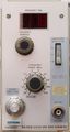
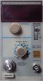
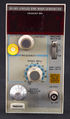
The Tektronix SG503 is a 250 MHz leveled sinewave generator plug-in for the TM500 system.
Nine overlapping ranges cover the frequency band from 250 kHz to 250 MHz, with an additional range reserved for a 50 kHz reference frequency.
It was primarily intended to be used as an oscilloscope calibration device for measuring bandwidths up to 250 MHz. Unlike later instruments like the SG504, it does not use a leveling head but was designed and calibrated with high quality coaxial cable (P/N 012-0482-00) to operate as a closely matched system when terminated into a 50 Ω load.
The SG503 shows the selected frequency on a 3-digit LED counter.
Key Specifications
| Frequency | 50 kHz, 250 kHz to 250 MHz in nine ranges |
|---|---|
| Frequency accuracy | Within ±0.7 of one count of the least significant displayed digit for the indicated frequency |
| Amplitude | 5 mVp-p to 5.5 Vp-p in three decade ranges (terminated into a 50 Ω load) |
| Harmonics | 2nd harmonic ≥35 dB down from fundamental, 3rd and higher harmonics ≥40 dB down |
Rear interface
The sine output, remote amplitude control input, and a 12-bit non-multiplexed BCD version of the counter value are available via the rear connector.
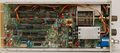
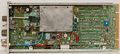
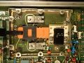
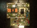
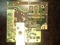
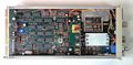
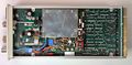
Internals
The SG503 uses two LC Hartley oscillators, one for 100 MHz and above with an air-core inductor, the other for the lower ranges using switched ferrite-core inductors. Tuning is accomplished via a traditional three-section variable capacitor. After filtering, a regulated power amplifier stage (caution: beryllium oxide in transistor cases!) is followed by a peak-to-peak detector for the amplitude control loop, and switchable output attenuators.
The frequency counter circuit starts with a ÷8 prescaler (SP1670 and 10131 ECL flip-flops) followed by 7490 TTL BCD counters and 7-segment decoders (display not multiplexed).
Notes
The Tek 012-0482-00 cable is made from RG-223 50 Ω double-braid shielded coaxial cable (or equivalent), and is exactly 36" from end-to-end.
Links
- SG503 @ amplifier.cd (German) including measurements of cable influence (1 m Belden H-155 as replacement for original cable)
- SG503 Peak-to-Peak detector substitute by John K. Bennett AE0AM
- SG503 Lab Check In and Calibration by Zenwizard Studios @ YouTube
- Tektronix SG503 Refresh and Alignments by Zenwizard Studios @ YouTube
Documents Referencing SG503
| Document | Class | Title | Authors | Year | Links |
|---|---|---|---|---|---|
| 070-2088-00.pdf | Book | TM500 Series Rear Interface Data Book | 1975 | AF501 • AM501 • AM502 • DC501 • DC502 • DC503 • DC504 • DC505 • DC505A • DM501 • DM502 • FG501 • FG502 • FG503 • MR501 • PG501 • PG502 • PG505 • PG506 • PG508 • PS501 • PS502 • PS503 • PS503A • PS505 • RG501 • SC501 • SC502 • SG502 • SG503 • TG501 | |
| 070-2088-01.pdf | Book | TM500 Series Rear Interface Data Book | 1976 | AF501 • AM501 • AM502 • AM511 • DC501 • DC502 • DC503 • DC504 • DC505 • DC505A • DD501 • DM501 • DM502 • FG501 • FG502 • FG503 • FG504 • LA501 • MR501 • PG501 • PG502 • PG505 • PG506 • PG508 • PS501 • PS502 • PS503 • PS503A • PS505 • RG501 • SC501 • SC502 • SG502 • SG503 • SG504 • SW503 • TG501 • TR501 • TR502 |
Prices
| Year | 1979 | 1980 |
|---|---|---|
| Catalog Price | $1,325 | $1,375 |
| In 2023 Dollars | $5,600 | $5,100 |
According to an internal memo, annual sales were estimated at 1200 units in 1979.
Pictures
Early model
-
-
-
Left Internal
-
Right Internal
-
Attenuator Board Part
-
Attenuator Board Top
-
Attenuator Board Bottom


Late model
-
-
-
Left Internal
-
Right Internal
-

-

-


Components
Some Parts Used in the SG503
| Part | Part Number(s) | Class | Description | Used in |
|---|---|---|---|---|
| 151-0614-00 | 151-0614-00 | Discrete component | Tek-made RF power transistor | SG503 |
| 155-0107-00 | 155-0107-00 | Hybrid integrated circuit | leveller | SG503 |