SW503: Difference between revisions
Jump to navigation
Jump to search
No edit summary |
No edit summary |
||
| Line 65: | Line 65: | ||
<gallery> | <gallery> | ||
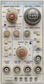
Tek SW503 front 1.jpg | Tek SW503 front 1.jpg | ||
Tek sw503 | Tek sw503 dc502 sg504 dc508a mr501 tm515.png|SW503 in [[TM515]] with other TM500 gear | ||
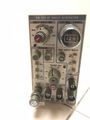
Tek sw503 front2.jpg | Tek sw503 front2.jpg | ||
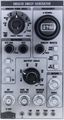
Tek sw503 front3.jpg | Tek sw503 front3.jpg | ||
</gallery> | |||
'''SW503 Opt.1''' | |||
<gallery> | |||
Tek sw503 opt1 1.jpg | Tek sw503 opt1 1.jpg | ||
Tek sw503 opt1 2.jpg | Tek sw503 opt1 2.jpg | ||
| Line 74: | Line 77: | ||
Tek sw503 opt1 4.jpg | Tek sw503 opt1 4.jpg | ||
Tek sw503 opt1 5.jpg | Tek sw503 opt1 5.jpg | ||
</gallery> | |||
'''SW503B''' | |||
<gallery> | |||
SW503B.jpg | SW503B catalog picture | SW503B.jpg | SW503B catalog picture | ||
</gallery> | </gallery> | ||
| Line 79: | Line 86: | ||
'''Internal''' | '''Internal''' | ||
<gallery> | <gallery> | ||
Tek | Tek SW503 left.jpg | ||
Tek | Tek SW503 right.jpg | ||
</gallery> | </gallery> | ||
==Components== | ==Components== | ||
{{Parts|SW503}} | {{Parts|SW503}} | ||
Latest revision as of 12:14, 1 March 2024

The Tektronix SW503 is a sweep generator plug-in for the TM500 system.
Key Specifications
| Frequency range | 1 to 400 MHz |
|---|---|
| Sweep width | 200 kHz to 400 MHz |
| Sweep time | 10 ms to 100 s, decade steps plus vernier |
| Output | −40 to +10 dBm into 50 Ω |
| Horizontal output | 0.5 Vp-p |
| Fixed markers | frequency comb with 1, 10, or 50 MHz base frequency |
| Variable marker | 1 to 400 MHz, digital readout on a DC502 Opt.07 counter |
| Features |
|
| Options |
|
Links
Documents Referencing SW503
| Document | Class | Title | Authors | Year | Links |
|---|---|---|---|---|---|
| 070-2088-01.pdf | Book | TM500 Series Rear Interface Data Book | 1976 | AF501 • AM501 • AM502 • AM511 • DC501 • DC502 • DC503 • DC504 • DC505 • DC505A • DD501 • DM501 • DM502 • FG501 • FG502 • FG503 • FG504 • LA501 • MR501 • PG501 • PG502 • PG505 • PG506 • PG508 • PS501 • PS502 • PS503 • PS503A • PS505 • RG501 • SC501 • SC502 • SG502 • SG503 • SG504 • SW503 • TG501 • TR501 • TR502 | |
| Tekscope 1976 V8 N1.pdf | Article | New Products | 1976 | FG504 • SG504 • LabCart Model 3 • SW503 • C-5A |
Rear Interface
| Connector Pin | Signal |
|---|---|
| 28B | Y axis output (common on 28A) |
| 27B | X axis output (common on 27A) |
| 24B | Trigger input (common on 25B) |
| 21B | Amplitude control input (0 – 10 V), common on 22B |
| 20B | Frequency control input (0 – 10 V), common on 22B |
| 18B | Start Count (0/+5 V; positive pulse to trigger the counter) |
| 18A | Gate (0/+5 V; negative gate from counter) |
| 17B | Counter Identify (grounded when counter is installed) |
| 16B | Phase Lock Logic (+5 V: 100 kHz resolution; 0 V: 10 Hz resolution) |
| 15B | CW Mode Logic (+5 V: dot marker function; 0 V: normal counter function) |
| 14B | Sweep Generator Identify (grounded when SW503 is installed) |
Pictures
External
-
-
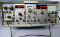
SW503 in TM515 with other TM500 gear
-
-


SW503 Opt.1


SW503B
-
SW503B catalog picture

Internal


Components
Some Parts Used in the SW503