WR501: Difference between revisions
(New page: <gallery> Image:wr501_front.jpg Image:wr501_left.jpg Image:wr501_left2.jpg Image:wr501_right.jpg Image:wr501_connector.jpg) |
No edit summary |
||
| (23 intermediate revisions by 3 users not shown) | |||
| Line 1: | Line 1: | ||
{{TM500 | mfg=Tektronix | type=WR501 | function=16-channel word recognizer | class=digital function | image=wr501_front.jpg | introduced=1976 | discontinued=(?) | | |||
designers=Pete Janowitz;Milt Klaudt;Dennis Glasby;Mike Lancaster |manuals= | |||
* [[Media:070-2168-00.pdf|WR501 Service Manual]] (OCR) | |||
* [https://w140.com/tek_wr501_1976_vol8no2_tekscope.pdf Article about WR501 and LA501 in Tekscope Magazine, 1976, Vol 8, No 2] | |||
* [https://w140.com/DD501-DL502-WR501.pdf Catalog Descriptions of DD501, DL502, and WR501] | |||
}} | |||
{{MissingSpecs}} | |||
The WR 501 word recognizer takes, as its inputs: | |||
* 16 digital input signals (through two [[P6451]] probes) | |||
* specification of the 16-bit trigger word, including any don't-care bits | |||
It produces a pulse at its output when the trigger word is recognized. | |||
==Links== | |||
{{Documents|Link=WR501}} | |||
==Internals== | |||
Most of the logic in the WR 501 is ECL, and is rated to operate up to about 50 MHz. | |||
It has synchronous (clocked) and asynchronous (unclocked) modes. | |||
The WR 501 includes a delay function and can provide a trigger signal for an oscilloscope or provide a trigger signal and data acquisition for the [[LA501]] Logic Analyzer. | |||
Note that DL15 and DL115, the 24-pin delay lines that fit in the sockets on each board are | |||
only found on units that were interconnected to an LA 501. The empty socket for DL15 is visible | |||
in the pictures below, on the A1 daughter board. The socket for DL115 is on the board underneath A1, | |||
on the A2 main board. They are unnecessary if you are using the WR501 to trigger a scope. | |||
These ECL delay lines, P/N 119-0775-00, 10 ns, 100 Ω, can be found in the [[7D01]] logic analyzer plugin for the [[7000-series scopes]]. | |||
==Pictures== | |||
<gallery> | <gallery> | ||
Wr501_front.jpg|Front | |||
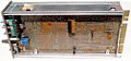
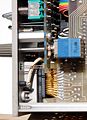
Wr501_left.jpg|Left internal | |||
Wr501_left2.jpg|Left internal | |||
WR501 with DL.jpg | Left internal (unit with delay line fitted) | |||
Wr501_right.jpg|Right internal | |||
Wr501_connector.jpg|Logic pod connector | |||
Tek wr501 block.png|Block diagram | |||
</gallery> | |||
Latest revision as of 09:16, 28 March 2024

The Tektronix WR501 is a 16-channel word recognizer plug-in for the TM500 system.
Key Specifications
- please add
The WR 501 word recognizer takes, as its inputs:
- 16 digital input signals (through two P6451 probes)
- specification of the 16-bit trigger word, including any don't-care bits
It produces a pulse at its output when the trigger word is recognized.
Links
Documents Referencing WR501
| Document | Class | Title | Authors | Year | Links |
|---|---|---|---|---|---|
| Tekscope 1976 V8 N2.pdf | Article | A Plug-in Word Recognizer with Digital Delay | Pete Janowitz | 1976 | WR501 • LA501 • LA501W |
Internals
Most of the logic in the WR 501 is ECL, and is rated to operate up to about 50 MHz. It has synchronous (clocked) and asynchronous (unclocked) modes.
The WR 501 includes a delay function and can provide a trigger signal for an oscilloscope or provide a trigger signal and data acquisition for the LA501 Logic Analyzer.
Note that DL15 and DL115, the 24-pin delay lines that fit in the sockets on each board are only found on units that were interconnected to an LA 501. The empty socket for DL15 is visible in the pictures below, on the A1 daughter board. The socket for DL115 is on the board underneath A1, on the A2 main board. They are unnecessary if you are using the WR501 to trigger a scope.
These ECL delay lines, P/N 119-0775-00, 10 ns, 100 Ω, can be found in the 7D01 logic analyzer plugin for the 7000-series scopes.
Pictures
-
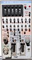
Front
-
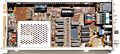
Left internal
-
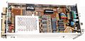
Left internal
-
Left internal (unit with delay line fitted)
-
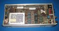
Right internal
-
Logic pod connector
-
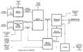
Block diagram


