191: Difference between revisions
Jump to navigation
Jump to search
No edit summary |
No edit summary |
||
| Line 1: | Line 1: | ||
[[ | {{Instrument Sidebar | ||
The '''Tektronix Type 191 Constant Amplitude Signal Generator''' is a sine wave source | |manufacturer=Tektronix | ||
[[introduced in 1966]]. | |model=191 | ||
|class=Signal generator | |||
|series= | |||
|summary=Constant Amplitude Signal Generator | |||
|image=Tek 191 front.jpg | |||
|caption=Tektronix 191 front | |||
|introduced=1966 | |||
|discontinued=(?) | |||
|designers= | |||
|manuals= | |||
* [[Media:070-0522-00.pdf|Tektronix 191 Manual]] (PDF) | |||
* [[Media:TB-9-6625-2176-35.pdf|TB-9-6625-2176-35 - 191 calibration]] | |||
* [[Media:Tek 191 fcp june 1966.pdf|Tektronix 191 Factory Calibration Procedure, June 1966]] | |||
}} | |||
The '''Tektronix Type 191 Constant Amplitude Signal Generator''' is a sine wave source [[introduced in 1966]]. | |||
{{MissingSpecs}} | {{MissingSpecs}} | ||
The 191 covers frequencies from 350 kHz to 100 MHz in seven bands. The output | The 191 covers frequencies from 350 kHz to 100 MHz in seven bands. | ||
amplitude can be adjusted in calibrated steps from 5 mV to 5 V in three ranges. | The output amplitude can be adjusted in calibrated steps from 5 mV to 5 V in three ranges. | ||
==Internals== | ==Internals== | ||
| Line 16: | Line 30: | ||
The calibration procedure in the manual makes use of a [[661]] to accurately view the output waveform. | The calibration procedure in the manual makes use of a [[661]] to accurately view the output waveform. | ||
==Pictures== | ==Pictures== | ||
| Line 33: | Line 42: | ||
</gallery> | </gallery> | ||
[[Category:Signal generators | [[Category:Signal generators]] | ||
[[Category:GR874]] | [[Category:GR874]] | ||
Revision as of 11:08, 18 August 2021

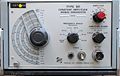
The Tektronix Type 191 Constant Amplitude Signal Generator is a sine wave source introduced in 1966.
Key Specifications
- please add
The 191 covers frequencies from 350 kHz to 100 MHz in seven bands. The output amplitude can be adjusted in calibrated steps from 5 mV to 5 V in three ranges.
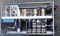
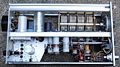
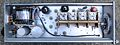
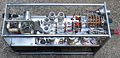
Internals
The oscillator is a Colpitts oscillator using a 7119 tube.
A peak-to-peak detector made with two GaAs diodes measures the swing of the oscillator and produces a DC feedback signal that controls a series voltage regulator that supplies power to the oscillator.
The calibration procedure in the manual makes use of a 661 to accurately view the output waveform.
Pictures
-
Front view
-
Top internal view
-
Bottom internal view
-
Left internal view
-
Right internal view
-
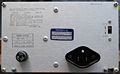
Rear view
-
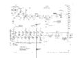
Schematic


