5116: Difference between revisions
No edit summary |
No edit summary |
||
| (26 intermediate revisions by 6 users not shown) | |||
| Line 1: | Line 1: | ||
[[ | {{Oscilloscope Sidebar |manufacturer=Tektronix |designers= |series=5000-series scopes| | ||
model= 5116 | | |||
summary=Color-display scope mainframe | | |||
image=5116.jpg | | |||
caption=Tektronix 5116 | | |||
introduced=1984 | | |||
discontinued=1987 | | |||
manuals= | |||
* [[Media:070-4544-00.pdf|Tektronix 5116 Manual (PDF)]] | |||
* [https://w140.com/tek_5116_5D10_specs.pdf Tektronix 5116 and 5D10 Specs (PDF)] | |||
* [[Media:52W-5522.pdf|Tektronix 5116 Brochure]] | |||
* [https://w140.com/Oscilloscopes_in_color_tek_5116.pdf Radio Electronics Article on Tek 5116 (PDF)] | |||
}} | |||
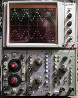
The '''Tektronix 5116''' is a single beam 2 MHz mainframe that has a two-colour LCD shutter in front of a CRT with P4 (white) [[phosphor]]. | |||
The color shutter works only with the [[5D10|5D10 digitizer plug-in]]. The 5116 manual says "The 5116 will not produce color | |||
signals if the 5D10 Waveform Digitizer does not have a serial number of B020100 or greater." | |||
The shutter consists of one red and one green polarizer/LCD combinations the size of the visible screen. | |||
The 5D10 in turn enables the red shutter, draws the red parts of display, turns on the green shutter in addition, draws | |||
the yellow (red+green) parts of the display, then turns off the red shutter, and draws the green parts of the display, | |||
at a rate of about 20 Hz. The slow multiplexing rate can lead to color artifacts becoming visible when the observer moves. | |||
In contrast with what is mentioned sometimes, the 5116 does '''not''' provide alphanumeric readout. The 5D10 takes care of this. | |||
{{MissingSpecs}} | |||
CRT: [[154-0871-00]], 4.5 kV acceleration | |||
==Pictures== | |||
<gallery> | |||
5116.jpg | |||
5116_01.jpg | |||
5D10tb.jpg | |||
5D10tracer.jpg | |||
5116 wo filter 1.jpg | |||
5116 wo filter 2.jpg | |||
Tek 5116 one trace.jpg | |||
Tek 5116 5d10 cursors.jpg|cursors | |||
Tek 5116 lvps fuses.jpg | |||
Tek 5116 bottom inside.jpg | |||
Tek 5116 hvps.jpg | |||
Tek 5116 deflection amps.jpg | |||
Tek 5116 right front board.jpg | |||
Tek 5116 left internal.jpg | |||
Tek 5116 lvps left.jpg | |||
Tek 5116 lvps right internal.jpg | |||
Tek 5116 plug-in bay.jpg | |||
</gallery> | |||
===Diagrams=== | |||
<gallery> | |||
Tek 5116 interface.png|Interface | |||
Tek 5116 vert and horiz amps.png|Vertical and Horizontal Amplifiers | |||
Tek 5116 crt circuit.png|CRT Circuit | |||
Tek 5116 lv power supply and calibrator.png|LV Power Supply and Calibrator | |||
Tek 5116 front panel board.png|Front Panel Board | |||
Tek 5116 interconnecting diagram.png|Interconnecting Diagram | |||
Tek 5116 signals out.png|Signal Out | |||
</gallery> | |||
[[Category:5000 series non-storage mainframes]] | |||
[[Category:Specifications needed]] | |||
[[Category:Introduced in 1984]] | |||
Latest revision as of 19:05, 5 January 2022
The Tektronix 5116 is a single beam 2 MHz mainframe that has a two-colour LCD shutter in front of a CRT with P4 (white) phosphor.
The color shutter works only with the 5D10 digitizer plug-in. The 5116 manual says "The 5116 will not produce color signals if the 5D10 Waveform Digitizer does not have a serial number of B020100 or greater."
The shutter consists of one red and one green polarizer/LCD combinations the size of the visible screen. The 5D10 in turn enables the red shutter, draws the red parts of display, turns on the green shutter in addition, draws the yellow (red+green) parts of the display, then turns off the red shutter, and draws the green parts of the display, at a rate of about 20 Hz. The slow multiplexing rate can lead to color artifacts becoming visible when the observer moves.
In contrast with what is mentioned sometimes, the 5116 does not provide alphanumeric readout. The 5D10 takes care of this.
Key Specifications
- please add
CRT: 154-0871-00, 4.5 kV acceleration
Pictures
-
-
-
-
-
-
-
-
cursors
-
-
-
-
-
-
-
-
-
Diagrams
-
Interface
-
Vertical and Horizontal Amplifiers
-
CRT Circuit
-
LV Power Supply and Calibrator
-
Front Panel Board
-
Interconnecting Diagram
-
Signal Out


