A6907: Difference between revisions
No edit summary |
No edit summary |
||
| (4 intermediate revisions by 2 users not shown) | |||
| Line 1: | Line 1: | ||
{{Instrument Sidebar | |||
|manufacturer= | |||
|model=A6907 | |||
|class=Isolator | |||
|series= | |||
|summary=High Voltage Isolator | |||
|image=Tek-A6907-A6909.jpg | |||
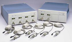
|caption=Tektronix A6907 / A6909 High Voltage Isolators | |||
|introduced=1995 | |||
|discontinued=(?) | |||
|designers= | |||
|manuals= | |||
* [[Media:070-9094-06.pdf|Tektronix A6907/A6909 User Manual]] | |||
* [[Media:071-0465-00.pdf|Tektronix A6907/A6909 Service Manual]] | |||
}} | |||
The '''Tektronix A6907 / A6909 High Voltage Isolators''' connect “floating” (not referenced to ground) signals to an oscilloscope or digitizer for measurement. | The '''Tektronix A6907 / A6909 High Voltage Isolators''' connect “floating” (not referenced to ground) signals to an oscilloscope or digitizer for measurement. | ||
| Line 23: | Line 37: | ||
}} | }} | ||
{{EndSpecs}} | {{EndSpecs}} | ||
==Internals== | ==Internals== | ||
| Line 34: | Line 44: | ||
<gallery> | <gallery> | ||
Tek a6909 1.jpg | Tek a6907 1.jpg|A6907 | ||
Tek a6909 2.jpg | Tek a6907 2.jpg|A6907 | ||
Tek a6907 3.jpg|A6907 | |||
Tek a6907 4.jpg|A6907 | |||
Tek a6909 1.jpg|A6909 | |||
Tek a6909 2.jpg|A6909 | |||
</gallery> | </gallery> | ||
[[Category:Amplifiers]] | [[Category:Amplifiers]] | ||
[[Category:GPIB interface]] | [[Category:GPIB interface]] | ||
Latest revision as of 03:13, 2 April 2024
The Tektronix A6907 / A6909 High Voltage Isolators connect “floating” (not referenced to ground) signals to an oscilloscope or digitizer for measurement.
The A6907 has four, the 6909 has two input channels.
The A6907/A6909 include special probes with an in-cable balun for shielding against large dv/dt fields. These probes are specific to the A6907/A6909.
Optionally, an A620 current probe can be connected.
Key Specifications
| Bandwidth | DC to 60 MHz (100 and 200 mV ranges: 50 MHz) |
|---|---|
| Deflection | 100 mV/Div to 200 V/Div, 1-2-5 (scope input @ 100 mV/Div) |
| Normal mode voltage | max. 850 V (DC + peak AC) |
| Common mode voltage (channel to chassis) | 850 V (DC + peak AC) or 600 V (ACRMS); derate at 20 dB/decade from 500 kHz to 60 MHz |
| Common mode voltage (between channels) | 1700 V (DC + peak AC) or 1200 V (ACRMS) |
| CMRR | 105 dB @ 60 Hz, 60 dB @ 1 MHz, 50 dB @ 10 MHz |
| Common mode slew rate | 20 kV/ms |
| Features |
|
Internals
Optical couplers, insulated transformers, and plastic barriers are used for extremely high isolation between channels and the chassis, and from channel to channel.
An electrical-to-optical (E/O) converter isolates the signal and converts it to an optical analogue. An optical-to-electrical (O/E) converter demodulates the optical signal to an electrical signal whose common mode elements have been rejected. The E/O converter uses a low-contact DC to DC converter as a power source to provide a high degree of isolation.
-
A6907
-
A6907
-
A6907
-
A6907
-
A6909
-
A6909


