175: Difference between revisions
No edit summary |
No edit summary |
||
| (23 intermediate revisions by 3 users not shown) | |||
| Line 1: | Line 1: | ||
The Tektronix | {{Instrument Sidebar | ||
The 175 uses the standard circuit topology for the collector supply: a variac followed by a | |manufacturer=Tektronix | ||
isolation transformer, followed by full-wave rectifiers. | |model=175 | ||
|class=Accessory | |||
|series= | |||
|summary=High-Current Curve Tracer Adapter | |||
|image=Tek 175 front2.jpg | |||
|caption=Tektronix 175 | |||
|introduced=1961 | |||
|discontinued=(?) | |||
|designers= | |||
|manuals= | |||
* [[Media:Tek 175 operating instructions.pdf|Tektronix 175 Operating Instructions]] | |||
* [[Media:Type 175 Calibration Procedure.pdf | Tektronix Type 175 Calibration Procedure]] | |||
}} | |||
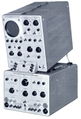
The '''Tektronix 175''', [[introduced in 1961]], is an external unit that extends the current capability of the [[575|575 curve tracer]]. | |||
The 175 uses the standard circuit topology for the collector supply: a variac followed by a multi-tap isolation transformer, followed by full-wave rectifiers. | |||
There are two modes: | There are two modes: | ||
* 0 - | * 0 - 20 V collector voltage, 200 A maximum collector current | ||
* 0 - | * 0 - 100 V collector voltage, 40 A maximum collector current | ||
Separate transformer taps and rectifiers are used for the two modes. | |||
In the 0-20 V mode, [[45L10]] rectifiers are used. | |||
Unlike the 575, which routes the test current through the front panel switches, the 175 routes the 0-20 V collector supply through 100 A relays, | |||
whose coil current are switched by the front panel (i.e., the "COLLECTOR POLARITY" and "TRANSISTOR SELECTOR") controls. | |||
Otherwise, the front panel switches would have to handle high currents and would be massive and difficult to operate. | |||
The front panel switches are break-before-make, which is important because if the relay coils were to be energized in the wrong combination, a short circuit would be formed. | |||
In the 0-100 V mode, the test current flows through the front panel switch. | |||
The Tektronix 175 requires a 575 to work, which provides +300 V, +100 V, and -150 V to power the step generator circuit in the 175. | |||
The cable that connects the 175 to the 575 uses [[Amphenol 165-15 connector|Amphenol 165-14 and 165-15 connectors]]. | |||
The front panel of the 175 has Superior Electric [[Supercon connector]]s for the high-current measurements. | |||
The positive (red) plug that goes into the 175 is a model PP100GR pin plug. | |||
The negative (black) plug that goes into the 175 is a model PS100GB socket plug. | |||
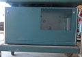
The 175 is 12"x13"x24" and weighs 38 kg (84 pounds). | |||
Most of the weight of the 175 is due to the large transformer | |||
([[Media:Tek 120-0197-00.pdf|part number 120-197]]) for the collector supply. | |||
==Pictures== | |||
<gallery> | <gallery> | ||
Tek 175 front.jpg|Front | |||
Tek 175 front2.jpg|Front | |||
Tek 175 left.jpg|Left | |||
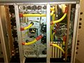
Tek 175 left open.jpg|Left internals | |||
Tek 175 right.jpg|Right | |||
Tek 175 right open.jpg|Right internals | |||
Tek 175 back.jpg|Rear | |||
Tek 175 step amp.png|Step amp | |||
Tek 175 switching diagram.png|Switching diagram | |||
Tek 175 collector sweep.png|Collector sweep | |||
Tek 175 bottom.jpg|Bottom view | |||
Tek 175 bus bar.jpg|Left internal | |||
Tek 575 on 175.jpg | |||
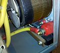
Tek 148-015 1.jpg|147-015 20 ampere relay used in 175 | |||
Tek 148-015 2.jpg|147-015 20 ampere relay used in 175 | |||
Tek 148-015 3.jpg|147-015 20 ampere relay used in 175 | |||
</gallery> | </gallery> | ||
==Components== | |||
{{Parts|175}} | |||
[[Category:Curve tracer plugins]] | |||
Latest revision as of 02:32, 14 May 2024

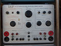
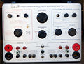
The Tektronix 175, introduced in 1961, is an external unit that extends the current capability of the 575 curve tracer.
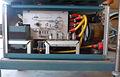
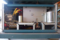
The 175 uses the standard circuit topology for the collector supply: a variac followed by a multi-tap isolation transformer, followed by full-wave rectifiers.
There are two modes:
- 0 - 20 V collector voltage, 200 A maximum collector current
- 0 - 100 V collector voltage, 40 A maximum collector current
Separate transformer taps and rectifiers are used for the two modes. In the 0-20 V mode, 45L10 rectifiers are used. Unlike the 575, which routes the test current through the front panel switches, the 175 routes the 0-20 V collector supply through 100 A relays, whose coil current are switched by the front panel (i.e., the "COLLECTOR POLARITY" and "TRANSISTOR SELECTOR") controls. Otherwise, the front panel switches would have to handle high currents and would be massive and difficult to operate. The front panel switches are break-before-make, which is important because if the relay coils were to be energized in the wrong combination, a short circuit would be formed. In the 0-100 V mode, the test current flows through the front panel switch.
The Tektronix 175 requires a 575 to work, which provides +300 V, +100 V, and -150 V to power the step generator circuit in the 175. The cable that connects the 175 to the 575 uses Amphenol 165-14 and 165-15 connectors.
The front panel of the 175 has Superior Electric Supercon connectors for the high-current measurements. The positive (red) plug that goes into the 175 is a model PP100GR pin plug. The negative (black) plug that goes into the 175 is a model PS100GB socket plug.
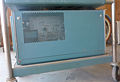
The 175 is 12"x13"x24" and weighs 38 kg (84 pounds). Most of the weight of the 175 is due to the large transformer (part number 120-197) for the collector supply.
Pictures
-
Front
-
Front
-
Left
-
Left internals
-
Right
-
Right internals
-
Rear
-
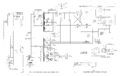
Step amp
-
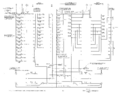
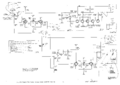
Switching diagram
-
Collector sweep
-
Bottom view
-
Left internal
-
-
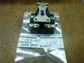
147-015 20 ampere relay used in 175
-
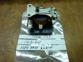
147-015 20 ampere relay used in 175
-
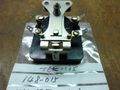
147-015 20 ampere relay used in 175


Components
Some Parts Used in the 175
| Part | Part Number(s) | Class | Description | Used in |
|---|---|---|---|---|
| 45L10 | Discrete component | stud-mounted rectifier | 175 |