549/Repairs: Difference between revisions
No edit summary |
No edit summary |
||
| (2 intermediate revisions by 2 users not shown) | |||
| Line 1: | Line 1: | ||
=== | ===Trace compressed on right side=== | ||
549 scopes from the Portland factory contain one black Aerovox 0.5 µF / 400 V capacitor in the horizontal amplifier (in the middle of the upper chassis) which is often deteriorated (leaky). When this is the case, the trace is compressed on the right side. To confirm, temporarily disconnect this capacitor and power on the scope with intensity control at CCW, and after initial warm-up of a minute increase the intensity to test if the problem disappears. | 549 scopes from the Portland factory contain one black Aerovox 0.5 µF / 400 V capacitor (C335) in the horizontal amplifier (in the middle of the upper chassis) which is often deteriorated (leaky). When this is the case, the trace is compressed on the right side. To confirm, temporarily disconnect this capacitor and power on the scope with intensity control at CCW, and after initial warm-up of a minute increase the intensity to test if the problem disappears. | ||
This capacitor is part of the beam steering arrangement during power-up to avoid screen burn. −150 V power on pulse is coupled | This capacitor is part of the beam steering arrangement during power-up to avoid screen burn. A −150 V power-on pulse is coupled to the R/C340 network in V343A's grid via this capacitor to move the beam to the left and off the screen during initial power up. The beam returns to screen after R/C340 discharges. | ||
The leaky capacitor can be replaced with a modern 0.47 µF / 630 V (or higher) capacitor. | The leaky capacitor can be replaced with a modern 0.47 µF / 630 V (or higher) capacitor. | ||
| Line 19: | Line 19: | ||
* Noted: R862 getting hot | * Noted: R862 getting hot | ||
* Root cause: Cathode choke (L862) hairline fracture of magnet wire | * Root cause: Cathode choke (L862) hairline fracture of magnet wire | ||
===No vertical amplification=== | |||
Caused by V514 side delay line short circuit. In the drawing you can see the resistive values measured without the transistors for the working model and for the non-working one. In the photo you can also see how the delay line has been replaced, being impossible to find it on the market. Surely the calibration will have to be done again but the instrument is usable. | |||
<gallery> | |||
Tek 549 connection side v514.jpg | Connection side v514 | |||
Tek 549 connections side L554 553.jpg | Connections side L554 553 | |||
Tek 549 temporary connections.jpg | Temporary/Provisional connections | |||
Tek 549 draft.jpeg | Schematics | |||
</gallery> | |||
[[Category:Instrument repair reports]] | [[Category:Instrument repair reports]] | ||
Latest revision as of 04:49, 28 August 2023
Trace compressed on right side
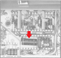
549 scopes from the Portland factory contain one black Aerovox 0.5 µF / 400 V capacitor (C335) in the horizontal amplifier (in the middle of the upper chassis) which is often deteriorated (leaky). When this is the case, the trace is compressed on the right side. To confirm, temporarily disconnect this capacitor and power on the scope with intensity control at CCW, and after initial warm-up of a minute increase the intensity to test if the problem disappears.
This capacitor is part of the beam steering arrangement during power-up to avoid screen burn. A −150 V power-on pulse is coupled to the R/C340 network in V343A's grid via this capacitor to move the beam to the left and off the screen during initial power up. The beam returns to screen after R/C340 discharges.
The leaky capacitor can be replaced with a modern 0.47 µF / 630 V (or higher) capacitor.
This problem does not appear to occur in Dutch-made 549s.
-
compressing trace on right side
-
Bad capacitor in horizontal amplifier schematic
-
Location of bad capacitor in horizontal amplifier
-
Location of bad capacitor in horizontal amplifier
Excessive brightness
- Symptom: Excessive brightness, intensity control inoperable
- Noted: R862 getting hot
- Root cause: Cathode choke (L862) hairline fracture of magnet wire
No vertical amplification
Caused by V514 side delay line short circuit. In the drawing you can see the resistive values measured without the transistors for the working model and for the non-working one. In the photo you can also see how the delay line has been replaced, being impossible to find it on the market. Surely the calibration will have to be done again but the instrument is usable.
-
Connection side v514
-
Connections side L554 553
-
Temporary/Provisional connections
-
Schematics


