1502: Difference between revisions
(Pulser TD update) |
No edit summary |
||
| Line 1: | Line 1: | ||
[[ | [[File:Tek1502-front.JPG|thumb|350px|right|Tektronix 1502 Time Domain Reflectometer (CRT version)]] | ||
The '''Tektronix 1502''' is a series of Time Domain Reflectometers commonly used to test coaxial | The '''Tektronix 1502''' is a series of Time Domain Reflectometers commonly used to test coaxial | ||
cables although they have many other uses. The US military was a major purchaser, most of the | cables although they have many other uses. The US military was a major purchaser, therefore most of the | ||
first series (the 1502, no letter) will be found surplus with some sort of US military | first series (the 1502, no letter) will be found surplus with some sort of US military | ||
property ID tag and an NSN sticker. | property ID tag and an NSN sticker. | ||
The first version used a CRT and is almost completely analog | ==Internals and version differences== | ||
The first version used a CRT and is an almost completely analog design except for some discrete digital | |||
logic used to pre-fire and fire the [[tunnel diodes|tunnel diode]] pulser. The later models (1502B/C) | logic used to pre-fire and fire the [[tunnel diodes|tunnel diode]] pulser. The later models (1502B/C) | ||
used | used a liquid-crystal display and a microprocessor. | ||
The other major difference between versions is the line charging method. | |||
The 1502 uses a fast (36 ps) tunnel diode pulser, the later models used a half sine wave to | The 1502 uses a fast (36 ps) tunnel diode pulser, the later models used a half sine wave to | ||
charge the line. The TD pulser, with its Dirac delta edge gives much better short range | charge the line. The TD pulser, with its Dirac delta edge, gives much better short range | ||
sensitivity although it is much easier to destroy. | sensitivity, although it is much easier to destroy. | ||
==Repair issues== | |||
There are four key parts in the 1502 that make repair difficult. The original sampling gate | There are four key parts in the 1502 that make repair difficult. The original sampling gate | ||
(CR1732, Tek [[152-0631-00]]) is no longer available, but Avago RF Schottky barrier diodes in | (CR1732, Tek [[152-0631-00]]) is no longer available, but Avago RF Schottky barrier diodes in | ||
the SOT series pair package (HSMS-2822, HSMS-282C) are a close substitute. These sampling bridges are so small and light that soldering them in place can be a frustrating experience. The leads are plated steel and if the soldering iron has a magnetic tip (e.g, many Weller models with temperature control), this can cause the gate to be attracted to the iron. Even with a non-magnetic iron such as a small 15-watt Antex, the surface tension of the solder is enough to cause the gate to "float" away from its intended mounting location when the iron is removed from the molten solder joint. A special "hold-down" device can be made to hold the bridge in place and was described in a Wizard's Workshop | the SOT series pair package (HSMS-2822, HSMS-282C) are a close substitute. These sampling bridges are so small and light that soldering them in place can be a frustrating experience. The leads are plated steel and if the soldering iron has a magnetic tip (e.g, many Weller models with temperature control), this can cause the gate to be attracted to the iron. Even with a non-magnetic iron such as a small 15-watt Antex, the surface tension of the solder is enough to cause the gate to "float" away from its intended mounting location when the iron is removed from the molten solder joint. A special "hold-down" device can be made to hold the bridge in place and was described in a Wizard's Workshop article. | ||
There is a [[snap-off diode]] (CR1632, Tek [[152-0335-01]]) in the sampling gate pulse shaper | There is a [[snap-off diode]] (CR1632, Tek [[152-0335-01]]) in the sampling gate pulse shaper | ||
that is also no longer available but it usually doesn't fail. | that is also no longer available but it usually doesn't fail. | ||
The first pulse shaping TD (CR1609, | The first pulse shaping TD (CR1609, Tek [[152-0140-01]], 10 mA, 8 pF) was a fairly common TD | ||
and there are [[Russian tunnel diodes|Russian substitutes available]]. The primary fast pulse TD (CR1703, Tek [[152-0489-00]], | and there are [[Russian tunnel diodes|Russian substitutes available]]. The primary fast pulse TD (CR1703, Tek [[152-0489-00]], | ||
21 mA, 1.5 pF) is simply no longer available. The | 21 mA, 1.5 pF) is simply no longer available. The closest Russian replacement is GI308E, it requires soldering to the original heatsink. | ||
If you want to design a replacement, I suggest looking at Analog Devices ADCMP580, and Starecki and Misiaszek's paper, | If you want to design a replacement, I suggest looking at Analog Devices ADCMP580, and Starecki and Misiaszek's paper, | ||
''[http://www.ise.pw.edu.pl/~tomi/papers/wilga2006_50ps.pdf Low cost programmable pulse generator with very short rise/fall time]''. | ''[http://www.ise.pw.edu.pl/~tomi/papers/wilga2006_50ps.pdf Low cost programmable pulse generator with very short rise/fall time]''. | ||
There appears to have been an optional "static suppressor" | There appears to have been an optional "static suppressor" in a BNC M-F package, Tek [[011-0132-00]], used to protect the sampler and TD. It's pretty obscure. The BNC connector on later 1502s contained an internal shorting bar that shorted the center conductor to the shell with no mating connector installed. In use, it was to short out the connecting cable so that any static on the line would be discharged before opening up the BNC connector to the internals of the TDR. Often, this shorting bar would break off, rendering the connector unable to discharge a cable to be connected. Replacing this BNC connector (or any front-panel component, for that matter) is a laborious process involving resealing the front panel for waterproofing. The original 1502 and 1503 were the first Tektronix instruments to be fully waterproof (with the X-Y Module installed) such that it could actually be operated while submerged to a shallow depth. The front panel sealing is a very involved process utilizing several different silicone (grease and RTV) products to do the job. Tektronix produced a separate Instuction Manual specifically for waterproofing details of the 1500-series. | ||
The other common failure is the battery. The power supply was designed to protect both the instrument | The other common failure is the battery. The power supply was designed to protect both the instrument | ||
| Line 48: | Line 51: | ||
==Pictures== | ==Pictures== | ||
<gallery> | <gallery> | ||
Tek1502-top.JPG|Top boards of the 1502 | |||
Tek1502-bottom.JPG|Underside of 1502 with stripline sampler and pulser exposed | |||
Tek1502-samplinggate.JPG|Sampling gate near the BNC end of stripline | |||
Tek1502-pulser.JPG|Pulser end of the stripline | |||
Tek1502-td.JPG|Pulser TD removed from stripline | |||
Tek1502-tdcurve.JPG|Pulser TD curve traced with a 576 | |||
Tek 1502 with printer.jpg|Tek 1502 with printer | |||
</gallery> | </gallery> | ||
| Line 60: | Line 63: | ||
[[Category:Time-domain reflectometers]] | [[Category:Time-domain reflectometers]] | ||
[[Category:Introduced in 1976]] | [[Category:Introduced in 1976]] | ||
= | |||
Revision as of 22:29, 28 June 2017

The Tektronix 1502 is a series of Time Domain Reflectometers commonly used to test coaxial cables although they have many other uses. The US military was a major purchaser, therefore most of the first series (the 1502, no letter) will be found surplus with some sort of US military property ID tag and an NSN sticker.
Internals and version differences
The first version used a CRT and is an almost completely analog design except for some discrete digital logic used to pre-fire and fire the tunnel diode pulser. The later models (1502B/C) used a liquid-crystal display and a microprocessor.
The other major difference between versions is the line charging method. The 1502 uses a fast (36 ps) tunnel diode pulser, the later models used a half sine wave to charge the line. The TD pulser, with its Dirac delta edge, gives much better short range sensitivity, although it is much easier to destroy.
Repair issues
There are four key parts in the 1502 that make repair difficult. The original sampling gate (CR1732, Tek 152-0631-00) is no longer available, but Avago RF Schottky barrier diodes in the SOT series pair package (HSMS-2822, HSMS-282C) are a close substitute. These sampling bridges are so small and light that soldering them in place can be a frustrating experience. The leads are plated steel and if the soldering iron has a magnetic tip (e.g, many Weller models with temperature control), this can cause the gate to be attracted to the iron. Even with a non-magnetic iron such as a small 15-watt Antex, the surface tension of the solder is enough to cause the gate to "float" away from its intended mounting location when the iron is removed from the molten solder joint. A special "hold-down" device can be made to hold the bridge in place and was described in a Wizard's Workshop article.
There is a snap-off diode (CR1632, Tek 152-0335-01) in the sampling gate pulse shaper that is also no longer available but it usually doesn't fail.
The first pulse shaping TD (CR1609, Tek 152-0140-01, 10 mA, 8 pF) was a fairly common TD and there are Russian substitutes available. The primary fast pulse TD (CR1703, Tek 152-0489-00, 21 mA, 1.5 pF) is simply no longer available. The closest Russian replacement is GI308E, it requires soldering to the original heatsink.
If you want to design a replacement, I suggest looking at Analog Devices ADCMP580, and Starecki and Misiaszek's paper, Low cost programmable pulse generator with very short rise/fall time.
There appears to have been an optional "static suppressor" in a BNC M-F package, Tek 011-0132-00, used to protect the sampler and TD. It's pretty obscure. The BNC connector on later 1502s contained an internal shorting bar that shorted the center conductor to the shell with no mating connector installed. In use, it was to short out the connecting cable so that any static on the line would be discharged before opening up the BNC connector to the internals of the TDR. Often, this shorting bar would break off, rendering the connector unable to discharge a cable to be connected. Replacing this BNC connector (or any front-panel component, for that matter) is a laborious process involving resealing the front panel for waterproofing. The original 1502 and 1503 were the first Tektronix instruments to be fully waterproof (with the X-Y Module installed) such that it could actually be operated while submerged to a shallow depth. The front panel sealing is a very involved process utilizing several different silicone (grease and RTV) products to do the job. Tektronix produced a separate Instuction Manual specifically for waterproofing details of the 1500-series.
The other common failure is the battery. The power supply was designed to protect both the instrument and the battery from abuse, so any failure will cause the power supply to latch up (via Q6547/Q6549) and the unit will appear dead. The pack is rebuildable with NiCd battery cells. To operate without a battery in place use a 200 to 270 Ω / 10 W power resistor in parallel with a 2200 μF cap (> 25 V); this will fool the power supply protection circuit into thinking that it's charging a valid battery.
Another common failure is a defective DISTANCE dial. Operators expect the numerical readout of this dial to go from zero to 999 and it is not designed to do that. Often, the internal plastic stops get broken from operators forcing the dial past its intended stop, rendering the part useless.
Manuals
- Tektronix 1502 Service Manual (PDF)
- Tektronix 1502B Service Manual (PDF)
- Tektronix 1502C Service Manual (PDF)
- Tektronix Chart Recorder User/Service Manual (PDF)
- Note that the manuals for the 1502B and 1503C are still available from Tektronix.
Pictures
-
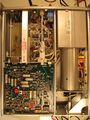
Top boards of the 1502
-
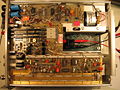
Underside of 1502 with stripline sampler and pulser exposed
-
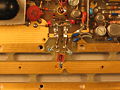
Sampling gate near the BNC end of stripline
-
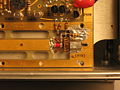
Pulser end of the stripline
-
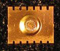
Pulser TD removed from stripline
-
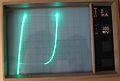
Pulser TD curve traced with a 576
-
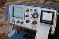
Tek 1502 with printer


=