067-0532-01: Difference between revisions
Jump to navigation
Jump to search
Brianbloom (talk | contribs) (Initial page layout. More to come.) |
No edit summary |
||
| Line 1: | Line 1: | ||
[[File:067-0532-01 front.JPG| | [[File:067-0532-01 front.JPG|350px|thumb|right|Tektronix 067-0532-01 Constant Amplitude Signal Generator]] | ||
The Tektronix '''Type 067-0532-01 Calibration Fixture''' is a '''Constant Amplitude Signal Generator''' whose output is a low-distortion sinewave. It is intended to provide a signal of known frequency and amplitude for measuring oscilloscope bandwidth | The Tektronix '''Type 067-0532-01 Calibration Fixture''' is a '''Constant Amplitude Signal Generator''' whose output is a low-distortion sinewave. It is intended to provide a signal of known frequency and amplitude for measuring oscilloscope bandwidth. | ||
A 3 MHz sinewave is available as a reference amplitude from which a -3 dB measurement can be made. The output connector, amplitude detector, and 50 Ω source resistor are at the end of a 42 inch cable. The amplitude is regulated at the end of the cable adjacent to the [[GR-874 connector|GR-874 output connector]], thus essentially eliminating cable loss and standing-wave errors. | |||
{{BeginSpecs}} | {{BeginSpecs}} | ||
{{SpecGroup| Frequency}} | |||
{{ | {{Spec | Range | 65 MHz to 500 MHz}} | ||
{{Spec | Range | | |||
{{Spec | Accuracy | Within 2% of indicated frequency }} | {{Spec | Accuracy | Within 2% of indicated frequency }} | ||
{{Spec | | {{Spec | 3 MHz Frequency Accuracy | Within 5%}} | ||
{{ | {{SpecGroup | Amplitude}} | ||
{{Spec | Range | 0. | {{Spec | Range | 0.5 V<sub>p-p</sub> to 4 V<sub>p-p</sub> into 50 Ω in 0.5 V increments}} | ||
{{Spec | Variable | Continuously | {{Spec | Variable | Continuously variable between calibrated steps. Max. output 4.2 V}} | ||
{{Spec | | {{Spec | 3 MHz Amplitude Accuracy | Within 2% of indicated amplitude}} | ||
{{ | {{SpecGroup | Constant Amplitude Accuracy}} | ||
{{Spec | | {{Spec | 65 MHz to 300 MHz | Within 2% of indicated amplitude}} | ||
{{Spec | | {{Spec | 300 MHz to 500 MHz | Within 5% of indicated amplitude}} | ||
{{Spec | Output Source Impedance | | {{Spec | Output Source Impedance | 50 Ω within 1%}} | ||
{{EndSpecs}} | {{EndSpecs}} | ||
| Line 27: | Line 26: | ||
* [http://w140.com/tek_067-0532-01.pdf Tektronix 067-0532-01 Manual (PDF)] | * [http://w140.com/tek_067-0532-01.pdf Tektronix 067-0532-01 Manual (PDF)] | ||
==Pictures== | ==Pictures== | ||
| Line 39: | Line 37: | ||
File:067-0532-01 signal gen circuit.JPG | Signal Generator Circuit | File:067-0532-01 signal gen circuit.JPG | Signal Generator Circuit | ||
File:067-0532-01 line filter.JPG | Line Filter Board | File:067-0532-01 line filter.JPG | Line Filter Board | ||
</gallery> | </gallery> | ||
[[Category:Signal generators]] | [[Category:Signal generators]] | ||
Revision as of 00:08, 25 February 2016

The Tektronix Type 067-0532-01 Calibration Fixture is a Constant Amplitude Signal Generator whose output is a low-distortion sinewave. It is intended to provide a signal of known frequency and amplitude for measuring oscilloscope bandwidth.
A 3 MHz sinewave is available as a reference amplitude from which a -3 dB measurement can be made. The output connector, amplitude detector, and 50 Ω source resistor are at the end of a 42 inch cable. The amplitude is regulated at the end of the cable adjacent to the GR-874 output connector, thus essentially eliminating cable loss and standing-wave errors.
Key Specifications
| — Frequency — | |
| Range | 65 MHz to 500 MHz |
| Accuracy | Within 2% of indicated frequency |
| 3 MHz Frequency Accuracy | Within 5% |
| — Amplitude — | |
| Range | 0.5 Vp-p to 4 Vp-p into 50 Ω in 0.5 V increments |
| Variable | Continuously variable between calibrated steps. Max. output 4.2 V |
| 3 MHz Amplitude Accuracy | Within 2% of indicated amplitude |
| — Constant Amplitude Accuracy — | |
| 65 MHz to 300 MHz | Within 2% of indicated amplitude |
| 300 MHz to 500 MHz | Within 5% of indicated amplitude |
| Output Source Impedance | 50 Ω within 1% |
Manuals
Pictures
-
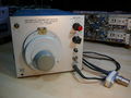
Front View
-
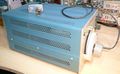
Left Side
-
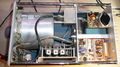
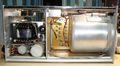
Top Internal
-
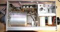
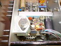
Bottom Internal
-
Left Internal
-

Right Internal
-
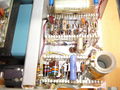
Signal Generator Circuit
-
Line Filter Board


