P6032: Difference between revisions
No edit summary |
No edit summary |
||
| Line 26: | Line 26: | ||
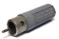
P6032_pwr.jpg|Internal view of power supply at end of P6032 cable. Signal coax passes through undisturbed. | P6032_pwr.jpg|Internal view of power supply at end of P6032 cable. Signal coax passes through undisturbed. | ||
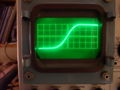
P6032_risetime.jpg|Display on [[545|545A]] with 1S1 and P6032. Pulse is generated by Tek [[284]] tunnel diode pulser driving into 50 ohm load, GR-BNC adaptor and then to the probe using a probe to BNC adaptor. The 10x attenuator tip was used on the P6032. Timebase is 200ps/div. | P6032_risetime.jpg|Display on [[545|545A]] with 1S1 and P6032. Pulse is generated by Tek [[284]] tunnel diode pulser driving into 50 ohm load, GR-BNC adaptor and then to the probe using a probe to BNC adaptor. The 10x attenuator tip was used on the P6032. Timebase is 200ps/div. | ||
Tek p6032 kit 1.jpg | |||
Tek p6032 kit 2.jpg | |||
Tek p6032 kit 3.jpg | |||
Tek p6032 kit 4.jpg | |||
</gallery> | </gallery> | ||
[[Category:Active Oscilloscope Probes]] | [[Category:Active Oscilloscope Probes]] | ||
Revision as of 19:14, 3 December 2017
The Tektronix P6032 is an 850 MHz cathode-follower probe, intended for use with samplers such as the 4S1, 3S76, and 1S1.
There is an EC1000 subminiature triode in the probe body, which is why it gets slightly warm during operation.
Like all active probes, the P6032 requires power, and for this reason it has two connectors at the scope end of cable. There is a four-pin power connector and a 50 Ω GR-874 connector for the signal.
The triode has limited dynamic range, so attenuator attachments are provided that attach to the tip of the probe. These attenuators also reduce the loading of the probe on the probed circuit.
What, exactly, does the clipping line in the probe body do? It appears to be 21 mm of RG-174 cable connected to the triode's cathode at one end, and open at the other end. The circuit description in the manual describes it vaguely, saying only that, "The clipping line reduces signal aberration to a minimum."
Manuals
Pictures
-
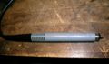
External view of P6032 without attenuator attachment.
-
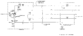
P6032 Schematic
-
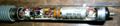
Internal view of P6032 Probe tip connects directly to triode grid, which is a bare wire coming out of the top of the tube. Clipping line runs along the body of the probe to the left of the tube socket.
-
×20 attenuator tip
-

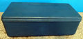
Internal view of power supply at end of P6032 cable. Signal coax passes through undisturbed.
-
-
-
-

-