132: Difference between revisions
No edit summary |
No edit summary |
||
| Line 1: | Line 1: | ||
{{Instrument Sidebar | |||
The '''Tektronix 132''' is an external enclosure, power supply, and amplifier | |manufacturer=Tektronix | ||
for a [[Letter-series_and_1-series_plug-ins|letter-series or 1-series plug-in]]. | |model=132 | ||
|class=Power supply | |||
|series=500-series scopes | |||
|summary=Module power supply | |||
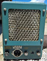
|image=132tq.jpg | |||
|caption=Tek 132 | |||
|introduced=1961 | |||
|discontinued=(?) | |||
|designers= | |||
|manuals= | |||
* [http://w140.com/tek_132.pdf Tektronix 132 Manual (PDF)] | |||
* [http://w140.com/tek_fcp/tek_type_132_factory_cal_proc.pdf Tektronix 132 Factory Calibration Procedure (PDF)] | |||
* [http://w140.com/tek_132_1968_catalog.pdf Tektronix 132 in 1968 Catalog (PDF)] | |||
}} | |||
The '''Tektronix 132''' is an external enclosure, power supply, and amplifier for a [[Letter-series_and_1-series_plug-ins|letter-series or 1-series plug-in]]. | |||
It was [[introduced in 1961]]. | It was [[introduced in 1961]]. | ||
The 132 supplies power to the plug-in and | The 132 supplies power to the plug-in and the signal output of the plug-in (i.e., at pins 1 and 3 of the plug-in's rear connector) is amplified by the three-stage DC-to-16 MHz all-tube differential amplifier in the 132. | ||
the signal output of the plug-in (i.e., at pins 1 and 3 of the plug-in's rear connector) | The resulting vertical signal is available on the front panel of the 132 either using [[UHF connector]]s (early 132 versions) or [[BNC connector]]s (late 132 versions). | ||
is amplified by the three-stage | |||
DC-to-16 MHz all-tube differential amplifier in the 132. | |||
The resulting vertical signal is available | |||
on the front panel of the 132 either using | |||
[[UHF connector]]s (early 132 versions) or | |||
[[BNC connector]]s (late 132 versions). | |||
The 132's power supply is similar to Tektronix oscilloscopes | The 132's power supply is similar to Tektronix oscilloscopes of the late 1950s and early 1960s. | ||
of the late 1950s and early 1960s. | The rectifier diodes are solid state, but the regulators are tube. | ||
The rectifier diodes are solid state, | An [[OG3]] tube is used to generate a -150 V reference voltage that is used for all of the other regulated voltages. | ||
but the regulators are tube. | The +225 V and +350 V supplies are floating supplies stacked on top of the +189 V unregulated DC that feeds the +100 V supply. | ||
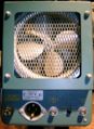
An [[OG3]] tube is used to generate a -150 V reference voltage that is used | The 132 has a fan that is always on when the power is on, and a 137 °F (58 °C) [[thermal cutoff]] for the rest of the circuitry. | ||
for all of the other regulated voltages. | |||
The + | |||
on top of the + | |||
The 132 has a fan that is always on when the power is on, | |||
and a | |||
The differential front panel output of the 132 has an output impedance of about | The differential front panel output of the 132 has an output impedance of about 5 kΩ per side. | ||
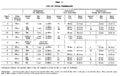
The gain and bandwidth of the entire system (plug-in + 132 + load) depend on the load impedance. | The gain and bandwidth of the entire system (plug-in + 132 + load) depend on the load impedance. | ||
For exact gain, the 132 needs to be terminated with an exact impedance. | For exact gain, the 132 needs to be terminated with an exact impedance. | ||
A load impedance of | A load impedance of 93 Ω maximizes bandwidth and further reductions of load impedance only reduce the available output swing. | ||
only reduce the available output swing. A load impedance of | A load impedance of 50 kΩ maximizes gain and further increases in load impedance have little effect on system performance. | ||
increases in load impedance have little effect on system performance. | |||
==Pictures== | ==Pictures== | ||
| Line 55: | Line 51: | ||
[[Category:Plugin power supplies]] | [[Category:Plugin power supplies]] | ||
Revision as of 09:11, 16 August 2021

The Tektronix 132 is an external enclosure, power supply, and amplifier for a letter-series or 1-series plug-in. It was introduced in 1961.
The 132 supplies power to the plug-in and the signal output of the plug-in (i.e., at pins 1 and 3 of the plug-in's rear connector) is amplified by the three-stage DC-to-16 MHz all-tube differential amplifier in the 132. The resulting vertical signal is available on the front panel of the 132 either using UHF connectors (early 132 versions) or BNC connectors (late 132 versions).
The 132's power supply is similar to Tektronix oscilloscopes of the late 1950s and early 1960s. The rectifier diodes are solid state, but the regulators are tube. An OG3 tube is used to generate a -150 V reference voltage that is used for all of the other regulated voltages. The +225 V and +350 V supplies are floating supplies stacked on top of the +189 V unregulated DC that feeds the +100 V supply. The 132 has a fan that is always on when the power is on, and a 137 °F (58 °C) thermal cutoff for the rest of the circuitry.
The differential front panel output of the 132 has an output impedance of about 5 kΩ per side. The gain and bandwidth of the entire system (plug-in + 132 + load) depend on the load impedance. For exact gain, the 132 needs to be terminated with an exact impedance. A load impedance of 93 Ω maximizes bandwidth and further reductions of load impedance only reduce the available output swing. A load impedance of 50 kΩ maximizes gain and further increases in load impedance have little effect on system performance.
Pictures
-
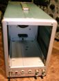
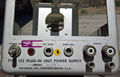
front view
-
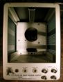
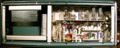
front inside
-
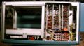
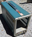
right view
-
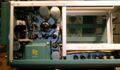
left view
-
bottom view
-
rear view
-
early 132
-
early 132
-
early 132
-
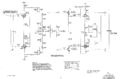
amplifier schematic
-
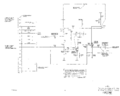
multi-trace sync schematic
-
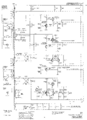
power supply schematic
-
gain and bandwidth


