112: Difference between revisions
No edit summary |
(cat) |
||
| Line 1: | Line 1: | ||
The Tektronix 112 is a DC-coupled differential amplifier [[introduced in 1955]]. | The '''Tektronix 112''' is a DC-coupled differential amplifier [[introduced in 1955]]. | ||
The voltage gain can be set from 0.5 to 5000 V/V. | The voltage gain can be set from 0.5 to 5000 V/V. | ||
The frequency response is DC to | The frequency response is DC to 2 MHz when the gain is set | ||
below 166, and DC to | below 166, and DC to 1 MHz for gain settings greater than that. | ||
The 121 is intended for use with the | The 121 is intended for use with the | ||
[[511]], [[512]], [[514]], and [[524]] oscilloscopes. | [[511]], [[512]], [[514]], and [[524]] oscilloscopes. | ||
The input impedance is 1 | The input impedance is 1 MΩ in parallel with 47 pF. | ||
The output impedance is 8000 | The output impedance is 8000 Ω. The amplifier's | ||
schematic and response are identical to that of a Tek 512. | schematic and response are identical to that of a Tek 512. | ||
| Line 15: | Line 15: | ||
The 112 has an unusual output coupling stage. | The 112 has an unusual output coupling stage. | ||
It provides output short circuit protection and | It provides output short circuit protection and | ||
shifts the common-mode DC level of the differential output to | shifts the common-mode DC level of the differential output to 0 V. | ||
The plate voltage of the final gain stage | The plate voltage of the final gain stage | ||
(just before the output coupling stage) is about + | (just before the output coupling stage) is about +150 V. | ||
When enabled, | When enabled, | ||
the output coupling stage is a a pair of constant current sinks. | the output coupling stage is a a pair of constant current sinks. | ||
| Line 23: | Line 23: | ||
This shunt current causes a constant voltage drop | This shunt current causes a constant voltage drop | ||
across output resistors, | across output resistors, | ||
resulting in | resulting in 0 V at the output. | ||
The cathodes of the output coupling stage are | The cathodes of the output coupling stage are | ||
supplied by the - | supplied by the -150 V rail, | ||
allowing them to operate as proper current sources | allowing them to operate as proper current sources | ||
when their plates are at 0V. | when their plates are at 0V. | ||
| Line 40: | Line 40: | ||
File:Tek 112 calibrator schematic.png|Calibrator Schematic | File:Tek 112 calibrator schematic.png|Calibrator Schematic | ||
</gallery> | </gallery> | ||
[[Category:Amplifiers]] | |||
[[Category:Introduced in 1955]] | |||
Revision as of 23:36, 17 August 2014
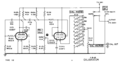
The Tektronix 112 is a DC-coupled differential amplifier introduced in 1955. The voltage gain can be set from 0.5 to 5000 V/V. The frequency response is DC to 2 MHz when the gain is set below 166, and DC to 1 MHz for gain settings greater than that. The 121 is intended for use with the 511, 512, 514, and 524 oscilloscopes. The input impedance is 1 MΩ in parallel with 47 pF. The output impedance is 8000 Ω. The amplifier's schematic and response are identical to that of a Tek 512.
The first stage is a differential amplifier using a pair of 5879 pentodes. Next is a differential amplifier using a pair of 12AU6 pentodes.
The 112 has an unusual output coupling stage. It provides output short circuit protection and shifts the common-mode DC level of the differential output to 0 V. The plate voltage of the final gain stage (just before the output coupling stage) is about +150 V. When enabled, the output coupling stage is a a pair of constant current sinks. It uses 6CB6 pentodes for this. This shunt current causes a constant voltage drop across output resistors, resulting in 0 V at the output. The cathodes of the output coupling stage are supplied by the -150 V rail, allowing them to operate as proper current sources when their plates are at 0V.
Internal photos needed.
-
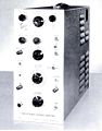
1955 Catalog photo
-
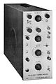
Manual photo
-
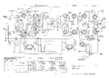
Main schematic
-
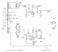
Power Supply Schematic
-
Calibrator Schematic


