213: Difference between revisions
Jump to navigation
Jump to search
Deanhuster (talk | contribs) (Cleanup) |
m (formatting (1st part)) |
||
| Line 18: | Line 18: | ||
==Specifications== | ==Specifications== | ||
===Digital Multimeter=== | |||
{{BeginSpecs}} | |||
{{Spec | DC Volts | 0.1 V to 1000 V, Input Resistance: 10MΩ <br />Accuracy, 0.1v & 1v: ±0.1%, ±3 counts; 10v & 100v: ±0.15%, ±1 count; 1000v: ±0.2%, ±1 count}} | |||
{{Spec | True RMS Volts | | |||
: 0.1v: ±2.5% (DC); ±1.5% (40 Hz – 4KHz); ±3.5% (4KHz – 40KHz) | |||
: 1, 10, 100v: ±2% (DC); ±1% (40Hz – 40KHz) | |||
: 1000v: ±2% (DC); ±1% (40 Hz – 4KHz); ±2% (4KHz – 40KHz) | |||
}} | |||
{{Spec | Current range input resistance | 0.1mA: 1000Ω; 1mA: 100Ω; 10mA: 10.2Ω; 100mA: 1.2Ω; 1000mA: 0.3Ω }} | |||
{{Spec | DC Current | | |||
: 0.1mA: ±0.5%, ±3 counts; 1mA – 1000mA: ±0.25%, ±3 counts | |||
}} | |||
{{Spec | True RMS Current | | |||
: 0.1mA: ±2.5%, ±5 counts (DC); ±1.5%, ±5 counts (40Hz – 4KHz); ±4.5%,±5 counts (4KHz - 40KHz) | |||
:1mA – 1000mA: ±2.5%, ±5 counts (DC); ±1.5%, ±5 counts (40Hz – 4KHz); ±3.5%,±5 counts (4KHz - 40KHz) | |||
}} | |||
{{Spec | Resistance | | |||
: 1KΩ: ±0.5%, ±3 counts; 10KΩ – 1MΩ: ±0.5%, ±1 count; 10MΩ: ±1%, ±1 count | |||
}} | |||
{{EndSpecs}} | |||
===Oscilloscope=== | |||
{{BeginSpecs}} | |||
{{Spec | Voltage ranges | 5 mV/Div to – 100 V/Div, ±3% }} | |||
{{Spec | Bandwidth (Voltage) | DC – 1 MHz (at 10 mV/Div and below, 400 kHz) }} | |||
{{Spec | Current ranges | 5 µA/Div to 100 mA/Div, ±3% }} | |||
{{Spec | Bandwidth (Current) | DC – 200 kHz (5 µA/Div – 10 µA/Div); DC – 400 kHz (20 µA/Div – 200 mA/Div) }} | |||
{{Spec | Input resistance | 10 MΩ // 150 pF (5 mV/Div – 1 V/Div), 100 pF (2 V/Div to – 100 V/DIv) }} | |||
{{Spec | Rise time | 875 ns (5mV – 10mV/DIV); 350 ns (20mV – 100v/DIV) }} | |||
{{Spec | Sweep | 500 ms/Div – 2 µs/Div, ±5% (magnified or unmagnified) }} | |||
{{Spec | Batteries | 2 × “D” NiCd cells }} | |||
{{Spec | Operating time | 3.5 hours typical at maximum intensity after full charge cycle}} | |||
{{Spec | Charge time | 16 h}} | |||
{{Spec | Mains power | 90 – 136 V<sub>AC</sub>. 48 – 62 Hz (Option 1: 180 – 250 V<sub>DC</sub>. or 180 – 250 V<sub>AC</sub>, 48 – 62 Hz) }} | |||
{{Spec | Power consumption | Less than 8 watts }} | |||
{{EndSpecs}} | |||
==Links== | ==Links== | ||
Revision as of 14:06, 16 September 2014

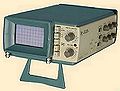
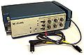
The Tektronix 213 is a miniature portable oscilloscope introduced in 1975. It combines a 3½-digit DMM and a 1 MHz single channel scope in one unit. The maximum sweep rate is 0.4 μs/div with ×10 sweep magnifier.
The 213 provides true RMS voltage and current measurements. It is battery or AC line powered.
Specifications
Digital Multimeter
Key Specifications
| DC Volts | 0.1 V to 1000 V, Input Resistance: 10MΩ Accuracy, 0.1v & 1v: ±0.1%, ±3 counts; 10v & 100v: ±0.15%, ±1 count; 1000v: ±0.2%, ±1 count |
|---|---|
| True RMS Volts |
|
| Current range input resistance | 0.1mA: 1000Ω; 1mA: 100Ω; 10mA: 10.2Ω; 100mA: 1.2Ω; 1000mA: 0.3Ω |
| DC Current |
|
| True RMS Current |
|
| Resistance |
|
Oscilloscope
Key Specifications
| Voltage ranges | 5 mV/Div to – 100 V/Div, ±3% |
|---|---|
| Bandwidth (Voltage) | DC – 1 MHz (at 10 mV/Div and below, 400 kHz) |
| Current ranges | 5 µA/Div to 100 mA/Div, ±3% |
| Bandwidth (Current) | DC – 200 kHz (5 µA/Div – 10 µA/Div); DC – 400 kHz (20 µA/Div – 200 mA/Div) |
| Input resistance | 10 MΩ // 150 pF (5 mV/Div – 1 V/Div), 100 pF (2 V/Div to – 100 V/DIv) |
| Rise time | 875 ns (5mV – 10mV/DIV); 350 ns (20mV – 100v/DIV) |
| Sweep | 500 ms/Div – 2 µs/Div, ±5% (magnified or unmagnified) |
| Batteries | 2 × “D” NiCd cells |
| Operating time | 3.5 hours typical at maximum intensity after full charge cycle |
| Charge time | 16 h |
| Mains power | 90 – 136 VAC. 48 – 62 Hz (Option 1: 180 – 250 VDC. or 180 – 250 VAC, 48 – 62 Hz) |
| Power consumption | Less than 8 watts |
Links
- EEVblog #628 – Tektronix 213 Vintage Portable Oscilloscope Teardown Video and Photo Set
- Tektronix 213 DMM Repair Progress video
Pictures
-
-
-
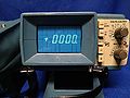
In DMM mode
-
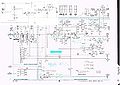
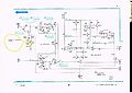
Attenuator and Input Amplifier Schematic
-
GM and RMS Converter Schematic
-
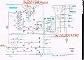
Battery Charger and Power Supply Schematic
-
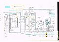
HV and CRT Schematic
-

A-D Converter and Character Generator Schematic


