513: Difference between revisions
No edit summary |
|||
| Line 42: | Line 42: | ||
==Vertical Signal Path== | ==Vertical Signal Path== | ||
The input impedance is 1 MΩ in parallel with 40 pF. | |||
The scope provides power to an optional cathode-follower probe. | |||
===Vertical Deflection Sensitivity and Bandwidth=== | |||
The 513 has a vertical deflection sensitivity switch with seven positions. | The 513 has a vertical deflection sensitivity switch with seven positions. | ||
Each position selects a range of sensitivities. | Each position selects a range of sensitivities. | ||
| Line 80: | Line 85: | ||
in common-cathode configuration, cascaded, followed by a cathode-follower stage | in common-cathode configuration, cascaded, followed by a cathode-follower stage | ||
using a [[12AT7]]. | using a [[12AT7]]. | ||
The | ===Delay Line=== | ||
When purchased with the delay line, the 513 is a 513D. | |||
The 513D was the first Tektronix oscilloscope to offer | |||
a [[delay line]] for the vertical signal, | a [[delay line]] for the vertical signal, | ||
to allow viewing the leading edge of the event that triggers the sweep. | to allow viewing the leading edge of the event that triggers the sweep. | ||
The delay line is single-ended, implemented using 40 L-C stages. | |||
===Phase Splitter=== | |||
Following the delay, a phase splitter produces two outputs, | |||
one inverted, one not inverted. | |||
These drive the distibuted vertical output amplifier. | |||
===Distributed Vertical Output Amplifier=== | |||
The 513 may have been the first Tektronix oscilloscope to contain a [[distributed amplifier]]. | The 513 may have been the first Tektronix oscilloscope to contain a [[distributed amplifier]]. | ||
It was released at about the same time as the [[514]], | It was released at about the same time as the [[514]], | ||
which contains a much simpler, lower bandwidth distributed amplifier. | which contains a much simpler, lower bandwidth distributed amplifier. | ||
The 513's distributed vertical output amplifier is seven | The 513's distributed vertical output amplifier is really two independent single-ended amplifiers, | ||
each containing seven stages of [[6CB6]] tubes. | |||
One output amplifier amplifies the inverted output of the phase splitter and | |||
drives one vertical deflection plate. | |||
The other output amplifier amplifies the noninverted output of the phase splitter and | |||
drives the other vertical deflection plate. | |||
The next scopes to use distributed amplifiers were | The next scopes to use distributed amplifiers were | ||
the [[517]] in 1951 and then the [[541]] and [[545]] in 1955. | the [[517]] in 1951 and then the [[541]] and [[545]] in 1955. | ||
==Low Voltage Power Supply== | ==Low Voltage Power Supply== | ||
Revision as of 18:09, 22 November 2014

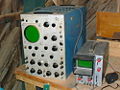
The Tektronix 513 is a single-channel monolithic oscilloscope with 18 MHz bandwidth.
History
It was announced in 1949 and introduced in 1950. The initial announcement in 1949 (link below) listed the 513 at $1695, weighing 60 pounds, with a low frequency cutoff of 5 Hz. As delivered to customers in 1950, the 513 weighed an extra 15 pounds, but had flat response down to DC and cost a bit less: $1650 with the delay line or $1600 without.
CRT
It used a 5XP CRT initially, and then switched to a Tek-made CRT.
Stan Griffiths says,
"The 513D used two different CRT types, depending on instrument serial number. From serial number 101-1887, the 5XP2 was used (Tek Part Number 154-066). From serial number 1888-up, the T51P2 was used (Tek pn 154-081). This one was made by Tek and you could retrofit it into the early 513Ds that came with the Dumont 5XP but it required a modification kit (040-0094-00). I have the instructions if you need them. Later, the 154-081 (also known as 154-0081-00) was replaced by the 154-0342-00 which is quite common and also used in the 530 series of scopes. If your 513D serial number is below 1888, the mod kit will have to be installed if you want to use this tube. I did not look at the mod instructions in detail, but often, with the instructions, you can put your own kit together and modify the scope just fine."
Vertical Signal Path
The input impedance is 1 MΩ in parallel with 40 pF.
The scope provides power to an optional cathode-follower probe.
Vertical Deflection Sensitivity and Bandwidth
The 513 has a vertical deflection sensitivity switch with seven positions. Each position selects a range of sensitivities. The positions of the vertical sensitivity switch are:
| Position | Bandwidth | Comments |
|---|---|---|
| 0.03 to 0.1 V/div | 2Hz to 16MHz | Preamplifier inserted in signal path. |
| 0.1 to 0.3 V/div | 2Hz to 16MHz | Preamplifier inserted in signal path. |
| 0.3 to 1 V/div | DC to 18MHz | |
| 1 to 3 V/div | DC to 18MHz | |
| 3 to 10 V/div | DC to 18MHz | |
| 10 to 30 V/div | DC to 18MHz | |
| 30 to 100 V/div | DC to 18MHz |
The exact sensitivity is determined by the position of the vertical amplifier attenuation control, which is a potentiometer.
The preamplifier for the two most sensitive ranges is made of two 12AW6 pentodes in common-cathode configuration, cascaded, followed by a cathode-follower stage using a 12AT7.
Delay Line
When purchased with the delay line, the 513 is a 513D. The 513D was the first Tektronix oscilloscope to offer a delay line for the vertical signal, to allow viewing the leading edge of the event that triggers the sweep. The delay line is single-ended, implemented using 40 L-C stages.
Phase Splitter
Following the delay, a phase splitter produces two outputs, one inverted, one not inverted. These drive the distibuted vertical output amplifier.
Distributed Vertical Output Amplifier
The 513 may have been the first Tektronix oscilloscope to contain a distributed amplifier. It was released at about the same time as the 514, which contains a much simpler, lower bandwidth distributed amplifier. The 513's distributed vertical output amplifier is really two independent single-ended amplifiers, each containing seven stages of 6CB6 tubes. One output amplifier amplifies the inverted output of the phase splitter and drives one vertical deflection plate. The other output amplifier amplifies the noninverted output of the phase splitter and drives the other vertical deflection plate.
The next scopes to use distributed amplifiers were the 517 in 1951 and then the 541 and 545 in 1955.
Low Voltage Power Supply
The 513 has no thermal cutoff and uses selenium rectifiers.
High Voltage Power Supply
The high voltages for the 513 CRT are generated by the Tektronix Type 210B High Voltage Power Supply,
The total CRT acceleration voltage of the 513 is 12kV. The cathode is at -2kV and the anode is a +10kV. The HV circuit uses four 5642 rectifier tubes, one for the cathode voltage and three for the anode voltage.
Mechanical
The 513 weighs 75 pounds and uses a maximum of 580 watts.
Specifications
please add
Pictures
-

-

-
-

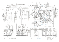
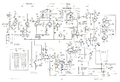
Block Diagram
-
Vertical Input and Cal
-
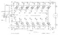
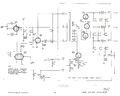
Distributed vertical amplifier.
-
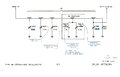
Delay Network
-

Delayed Gate and Trigger
-

Trigger Rate Generator
-
Sweep
-
High Voltage Oscillator
-

Power Supply
-
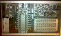
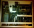
Top internal view. Delay is at lower right.
-
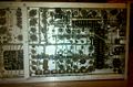
Right internal view.
-
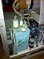
High voltage power supply
-

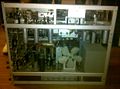
Right external view.
-
Left internal. 5XP CRT has three anode connections.
-
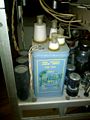
High voltage power supply
-

-
Bottom view.
-
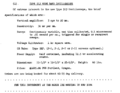
Announcement in 1949 Sales Brochure


