549: Difference between revisions
No edit summary |
(Power Supply Description) |
||
| Line 70: | Line 70: | ||
There is a remote control cable/switch, | There is a remote control cable/switch, | ||
part number 012-0102-00 (photo below), that can erase the screen and reset the single sweep. | part number 012-0102-00 (photo below), that can erase the screen and reset the single sweep. | ||
===Low Voltage Power Supply=== | |||
549 Low Voltage Power Supply provides voltage for all the stages and heater voltage. It provides DC -12.4V, -150V, +100V, +225V, +300V, +350V, +500 regulated output and +475V Unregulated output. | |||
Line input is connected to main transformer primary via two switches, one to select 110/230V Range - (which is inside the chassis) and another switch (on the rear of the chassis) to select Low/Medium/High voltage range in both the above line voltage class. | |||
Multiple secondary windings feeds diodes for rectification for different voltages. Both center-tap and bridge configuration is used. | |||
Transistors and/or Tubes are used for regulation. | |||
The design regulates one power rail (of -150V in this case) and refer all other voltage rails to this output to keep all voltages stable. | |||
This enables adjusting all rail voltages with one Trim resistor/Potentiometer. | |||
5651 VR Tube is used as the reference for -150V, 12AX7 is used as the Comparator, 3 Nos of 12B4 are used as series regulator tubes. 6AU6 is used as error amplifier. | |||
Most other stages replicate the same design, except slight changes in Tubes used,6080 Tube is used as series regulator for +350V, +225V and +100V | |||
The -12.4V rail is all transistor regulator. | |||
A thermal delay tube which controls a relay is used to delay the plate voltages to the Tubes till they are warmed up. On power up, only heater voltage is applied to the tubes, which also drives the thermal delay tube. After a time delay of up to 60 seconds, the thermal delay tube activates the relay, powering all outputs ON. Unregulated +100V is used to drive this relay. | |||
The circuit is designed such that Thermal delay tube cut itself off the circuit once it turns the relay and outputs on, but holding the relay on. | |||
This allows the thermal delay tube to cool down and allow heater warmup time even after a quick interrupt in power input. | |||
==Links== | ==Links== | ||
Revision as of 16:00, 17 February 2018

The Tektronix 549 is the only storage scope that takes a letter-series or 1-series vertical plug-in.
It was introduced in 1966 and discontinued after 1973.
Key Specifications
| Bandwidth | DC to 30 MHz (at -3 dB Point), depending on vertical plug-in |
|---|---|
| Rise time | 12 ns |
| Deflection Factor | 100 mV/Div |
| Line Voltage | 104/115/127/208/230 VAC ±10%,selected via primary voltage selector and voltage range selector Switches, 50 Hz to 60 Hz. |
| Thermal Protection | Automatic resetting thermal cutout, in case internal temperature exceeds safe operating level |
| Power Consumption | 650 W, 750 VA |
| Size | 13W x 24L x 17H Inches or 43.2W x 32.9L x 60.7L cm |
| Weight | 68 lb or 31Kg |
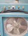
| Cooling | AC Fan |
| Construction | Aluminum alloy chassis. Anodized front panel. Blue vinyl coated cabinet |
Internals
Mix of Transistors and Tubes
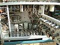
Like many Tek scopes from the period, the 549 uses a mix of transistors and tubes. For example, consider the buffer amplifier in the 549, whose purpose is to interface the high-impedance output of the plug-in with the low-impedance of the 200 ns delay line in the 549. As is usual in oscilloscope vertical circuits, the requirement is to have flat frequency response from DC to the maximum frequency of the scope and to have linear phase response over this same frequency range.
In the 549, this buffer is implemented as follows: A 6DJ8 tube configured as a cathode follower is used at the interface with the plug-in to present a high impedance to the plug-in. This input stage drives an NPN BJT differential amplifier, which operates at the bottom of a cascode configuration with a 7119 tube on top. The output of the cascode (the plate of the 7119) drives the delay line.
Since the entire signal path is differential, the common-mode voltage does not have to be zero, and it is not; the differential signal in the delay line rides on 167 volts of DC. After the delay line, the signal enters another cascoded differential amplifier with NPN BJTs on the bottom and 8608 tubes on the top.
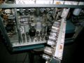
The vertical deflection plates of the CRT are driven by the plates of an 8608 10-watt power pentode through inductive matching/peaking networks.
Non-Distributed Amplifier
The 549 is slightly unusual among 54x-series scopes in that it does not use a distributed vertical amplifier. (Other exceptions include the 545B and 547).
Triggering
Triggering is done using an NPN BJT Schmitt trigger.
Storage
The 549 uses the T5490 CRT.
The screen has two storage targets, upper and lower, whose storage mode and erase signals can be controlled independently. There is a remote control cable/switch, part number 012-0102-00 (photo below), that can erase the screen and reset the single sweep.
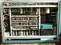
Low Voltage Power Supply
549 Low Voltage Power Supply provides voltage for all the stages and heater voltage. It provides DC -12.4V, -150V, +100V, +225V, +300V, +350V, +500 regulated output and +475V Unregulated output.
Line input is connected to main transformer primary via two switches, one to select 110/230V Range - (which is inside the chassis) and another switch (on the rear of the chassis) to select Low/Medium/High voltage range in both the above line voltage class.
Multiple secondary windings feeds diodes for rectification for different voltages. Both center-tap and bridge configuration is used. Transistors and/or Tubes are used for regulation.
The design regulates one power rail (of -150V in this case) and refer all other voltage rails to this output to keep all voltages stable. This enables adjusting all rail voltages with one Trim resistor/Potentiometer.
5651 VR Tube is used as the reference for -150V, 12AX7 is used as the Comparator, 3 Nos of 12B4 are used as series regulator tubes. 6AU6 is used as error amplifier.
Most other stages replicate the same design, except slight changes in Tubes used,6080 Tube is used as series regulator for +350V, +225V and +100V
The -12.4V rail is all transistor regulator.
A thermal delay tube which controls a relay is used to delay the plate voltages to the Tubes till they are warmed up. On power up, only heater voltage is applied to the tubes, which also drives the thermal delay tube. After a time delay of up to 60 seconds, the thermal delay tube activates the relay, powering all outputs ON. Unregulated +100V is used to drive this relay.
The circuit is designed such that Thermal delay tube cut itself off the circuit once it turns the relay and outputs on, but holding the relay on. This allows the thermal delay tube to cool down and allow heater warmup time even after a quick interrupt in power input.
Links
- Rajesh's Tek 549 Restoration
- Tektronix, the Storage Story (1966) @ radiomuseum.org
- A 549 @ YouTube
Pictures
-
-
-
-
-
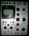
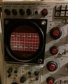
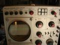
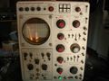
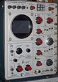
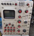
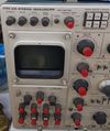
Front of a 549.
-
Vertical amp.
-
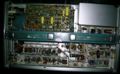
Top view.
-
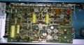
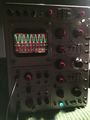
Storage board.
-
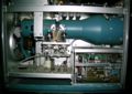
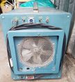
Power supply behind door.
-
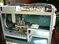
Right side internal.
-
-
-

-

012-0102-00 remote control for 549
-
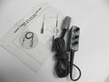
012-0102-00 remote control for 549
-

549 with Rectangular Bezel
-
-
-
-
-
-

B INTEN BY A Trig in 549
-
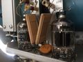
8608 Vertical Output Tubes of 549
-
Dual Trace in 549
-
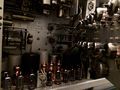
549 LV Power Supply Tubes
-
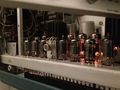
549 LV Power Supply Tubes


