465: Difference between revisions
Jump to navigation
Jump to search
(→Links) |
No edit summary |
||
| Line 37: | Line 37: | ||
{{BeginSpecs}} | {{BeginSpecs}} | ||
{{Spec | Bandwidth | DC to | {{Spec | Bandwidth | DC to 100 MHz on CH1 & CH2 for -15°C to +40°C and DC to 85 MHz from +40°C to +55°C}} | ||
{{Spec | Rise time | 3. | {{Spec | Rise time | 3.5 ns for 0°C to +40°C and 4.2 ns from +40°C to +55°C}}} | ||
{{Spec | | {{Spec | Input Impedance | 1 MΩ ±2% // 20 pF }} | ||
{{Spec | Maximum Input Voltage - AC Coupled | 500V DC + Peak AC or 500V<sub>p-p</sub> AC at < 1kHz }} | {{Spec | Maximum Input Voltage - AC Coupled | 500V DC + Peak AC or 500V<sub>p-p</sub> AC at < 1kHz }} | ||
{{Spec | Maximum Input Voltage - DC Coupled | 250V DC+ Peak | {{Spec | Maximum Input Voltage - DC Coupled | 250V DC + Peak AC or 500V<sub>p-p</sub> AC at < 1kHz }} | ||
{{Spec | Trigger Coupling Modes | DC, AC, LF Reject, HF Reject}} | {{Spec | Trigger Coupling Modes | DC, AC, LF Reject, HF Reject}} | ||
{{Spec | Channel Isolation | 100:1 at | {{Spec | Channel Isolation | 100:1 at 25 MHz }} | ||
{{Spec | Z Axis Input | | {{Spec | Z Axis Input | 5 V<sub>p-p</sub> signal causes noticeable modulation at normal intensity }} | ||
{{Spec | Z Axis Frequency response | DC to | {{Spec | Z Axis Frequency response | DC to 50 MHz }} | ||
{{Spec | Output Signals | CH1 Vertical, A & B +Gate}} | {{Spec | Output Signals | CH1 Vertical, A & B +Gate}} | ||
{{Spec | Calibrator Output | ~ | {{Spec | Calibrator Output | ~1 kHz, 300 mV, Square Wave}} | ||
{{Spec | CRT Graticule Area | | {{Spec | CRT Graticule Area | 8 cm × 10 cm }} | ||
{{Spec | CRT Phosphor| P31 }} | {{Spec | CRT Phosphor| P31 }} | ||
{{Spec | CRT Accelerating Potential | 18. | {{Spec | CRT Accelerating Potential | 18.5 kV }} | ||
{{Spec | Line Voltage | 110/115/120/220/ | {{Spec | Line Voltage | 110/115/120/220/240 V<sub>AC</sub> ±10%, selected via primary voltage selector and regulating Range range selector assembly, 48 Hz to 440 Hz. }} | ||
{{Spec | Power Consumption | 75 W @ | {{Spec | Power Consumption | 75 W @ 115 V<sub>AC</sub> / 60 Hz}} | ||
{{EndSpecs}} | {{EndSpecs}} | ||
Revision as of 05:12, 1 August 2018
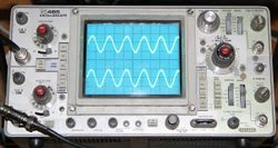
The Tektronix 465 is a portable 100 MHz dual-trace oscilloscope with dual time-bases.
The 465 was very popular and Tek made them for quite a few years.
It is all solid-state except for the CRT. It was introduced in November 1972.
Bill Turner worked as a calibration technician for the 465 oscilloscope group.
There was no 465A but a 465B (int. 1980) with the same base specs but improved performance. The 475 is a 200 MHz sister model.
The optional DM44 multimeter attaches to the top of the instrument.
See also 465M.
Key Specifications
}| Bandwidth | DC to 100 MHz on CH1 & CH2 for -15°C to +40°C and DC to 85 MHz from +40°C to +55°C |
|---|---|
| Rise time | 3.5 ns for 0°C to +40°C and 4.2 ns from +40°C to +55°C |
| Input Impedance | 1 MΩ ±2% // 20 pF |
| Maximum Input Voltage - AC Coupled | 500V DC + Peak AC or 500Vp-p AC at < 1kHz |
| Maximum Input Voltage - DC Coupled | 250V DC + Peak AC or 500Vp-p AC at < 1kHz |
| Trigger Coupling Modes | DC, AC, LF Reject, HF Reject |
| Channel Isolation | 100:1 at 25 MHz |
| Z Axis Input | 5 Vp-p signal causes noticeable modulation at normal intensity |
| Z Axis Frequency response | DC to 50 MHz |
| Output Signals | CH1 Vertical, A & B +Gate |
| Calibrator Output | ~1 kHz, 300 mV, Square Wave |
| CRT Graticule Area | 8 cm × 10 cm |
| CRT Phosphor | P31 |
| CRT Accelerating Potential | 18.5 kV |
| Line Voltage | 110/115/120/220/240 VAC ±10%, selected via primary voltage selector and regulating Range range selector assembly, 48 Hz to 440 Hz. |
| Power Consumption | 75 W @ 115 VAC / 60 Hz |
Internals
The 465 uses tunnel diodes with Tek part number 152-0125-00, which are equivalent to TD3A, and 155-0032-00 chips (their -01 grade) as trigger amplifiers. The CRT is part number 154-0676-10.
Links
- Rajesh's Tek 465 Repair
- The New Look in Portables, in Tekscope Vol. 4 No. 5, 1972
- Jim Williams repairs Tom Osborne's Tektronix 465B oscilloscope (YouTube)
- Another successful 465 repair, shorted tantalum (YouTube)
- Repairing a 465 (power supply, z axis amplifier, vertical pre amplifier issues) - nice internal photos
- Tek 465 page @ amplifier.cd
- 465B differences
- Tek 465 "teardown"
- Replacing Electrolytic Filter Capacitors in a Tektronix 465


