130: Difference between revisions
No edit summary |
(Link to manual (bama) for earlier model cabinet design, SN Range update) |
||
| Line 11: | Line 11: | ||
There are at least two versions of Type 130. | There are at least two versions of Type 130. | ||
Early units have a narrow boxy case that slides off the chassis, brown paint, backlit meter, and are marked "TYPE 130 L,C METER". | Early units (SN 101-5000) have a narrow boxy case that slides off the chassis, brown paint, backlit meter, and are marked "TYPE 130 L,C METER". | ||
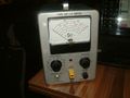
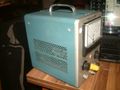
Later units have a wider rounded case with side panels that pop off, blue paint, non-backlit meter, and are marked "TYPE 130 L-C METER". | Later units (SN 5001-Up)have a wider rounded case with side panels that pop off, blue paint, non-backlit meter, and are marked "TYPE 130 L-C METER". | ||
{{BeginSpecs}} | {{BeginSpecs}} | ||
| Line 23: | Line 23: | ||
==Manuals== | ==Manuals== | ||
* [http://bama.edebris.com/download/tek/130/Tek-130_LC_Meter.pdf Tektronix 130 Manual (PDF)] | * [http://bama.edebris.com/download/tek/130/Tek-130_LC_Meter.pdf Tektronix 130 Manual 070-231 (PDF)] | ||
* [http://bama.edebris.com/download/tek/130/tek130.pdf Tektronix 130 Manual 070-231-01 (PDF) (Covering both cabinet types) ] | |||
* [http://w140.com/tek_fcp/tek_type_130_factory_cal_proc.pdf Tektronix 130 Factory Calibration Procedure (PDF)] | * [http://w140.com/tek_fcp/tek_type_130_factory_cal_proc.pdf Tektronix 130 Factory Calibration Procedure (PDF)] | ||
Revision as of 17:20, 28 May 2020

The Tektronix Type 130 is a self-contained instrument that measures inductance and capacitance. The 130 makes an LC oscillator using the device under test and a capacitor or inductor internal to the 130. That oscillator's frequency is measured by mixing it down using a fixed reference frequency, generating a pulse at each zero-crossing, and integrating (low-pass filtering) the pulse train. This produces a voltage that is proportional to the frequency difference between the LC oscillator and the reference oscillator. This voltage is displayed on a d'Arsonval (moving coil) meter on the front panel of the 130.
The Type 130 was designed by Cliff Moulton.
There are at least two versions of Type 130. Early units (SN 101-5000) have a narrow boxy case that slides off the chassis, brown paint, backlit meter, and are marked "TYPE 130 L,C METER". Later units (SN 5001-Up)have a wider rounded case with side panels that pop off, blue paint, non-backlit meter, and are marked "TYPE 130 L-C METER".
Key Specifications
| Ranges | 3, 10, 30, 100 or 300 pF / 3, 10, 30, 100 or 300 μH full scale |
|---|---|
| Accuracy | 3% FS, 1% FS with "careful" calibration using S-30 Delta Standard |
| Measurement voltage | <1 V for capacitors, <0.25 V for inductors, 120-140 kHz |
| Guard output | 250 Ω source impedance, can drive 200 pF |
| DUT connection | UHF connector (DUT) + 4 mm jack (guard) |
Manuals
- Tektronix 130 Manual 070-231 (PDF)
- Tektronix 130 Manual 070-231-01 (PDF) (Covering both cabinet types)
- Tektronix 130 Factory Calibration Procedure (PDF)
Links
- Q+A: Type 130 L-C Meter and S-30 Delta Standards. Service Scope No. 18, Feb 1963.
Pictures
-
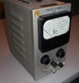
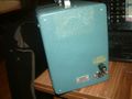
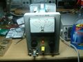
Early (Brown Era) Type 130
-
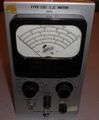
Early (Brown Era) Type 130
-
-
-
-
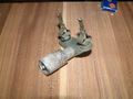
013-0001-00 test adapter
-
-
-
-
-
-
-
-
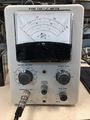
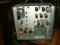
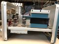
Type 130 Front
-
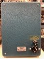
Type 130 Rear
-
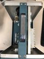
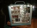
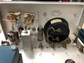
Type 130 Top w/o Cover
-
Type 130 Bottom
-

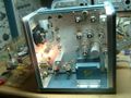
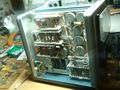
Type 130 Internal RHS
-
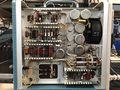
Type 130 Internal LHS
-
Type 130 Internal #1
-
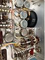
Type 130 Internal #1
-
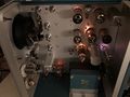
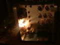
Type 130 Internal Live


