422: Difference between revisions
(Pic w Trace) |
(Rearranged Pics) |
||
| Line 52: | Line 52: | ||
==Pictures== | ==Pictures== | ||
=== External=== | |||
<gallery> | <gallery> | ||
Tek 422 front.jpg | Tek 422 front.jpg | ||
Tek 422 side.jpg | Tek 422 side.jpg | ||
Tek | Tek r422 1.jpg|R422, compartment closed | ||
Tek 422 | Tek r422 2.jpg|R422, compartment open | ||
Tek 422 | Black tek 422.jpg|Black 422, panel mount | ||
Tek 422 | Tek 422 triag trace.jpg | ||
Tek 422 | Tek 422 tight beam.jpg|422 trace is sharp | ||
Tek 422 | Tek_222_wtrace2.jpeg | 422 in ALT | ||
Tek 422 34.JPG | |||
Tek 422 342.JPG | |||
422 mpf102 cal.jpg | 422 mpf102 cal.jpg | ||
</gallery> | |||
=== Internal=== | |||
<gallery> | |||
422 8056 mpf102.jpg|[[MPF102]] replacing [[8056]] | |||
Wellenkino 422.jpg | |||
Tek 422 front part rear.jpg | Tek 422 front part rear.jpg | ||
Tek 422 left int.jpg | Tek 422 left int.jpg | ||
| Line 72: | Line 79: | ||
Tek 422 vert amp2.jpg | Tek 422 vert amp2.jpg | ||
Tek 422 vert input amps.jpg | Tek 422 vert input amps.jpg | ||
</gallery> | |||
=== Schematic=== | |||
<gallery> | |||
Tek 422 trigger.png|Trigger circuit | |||
Tek 422 sweep.png|Sweep circuit | |||
Tek 422 vertamp.png|Vertical amplifier circuit | |||
Tek 422 inputamp.png|Input amplifier circuit | |||
Tek 422 horizamp.png|Horizontal amplifier circuit | |||
Tek 422 crt.png|CRT circuit | |||
Tek-422 lvps2.png|ac-dc power supply | Tek-422 lvps2.png|ac-dc power supply | ||
Tek 422 acps.png|ac power supply | Tek 422 acps.png|ac power supply | ||
</gallery> | </gallery> | ||
[[Category:400 series scopes]] | [[Category:400 series scopes]] | ||
Revision as of 12:42, 7 June 2020

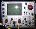
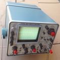
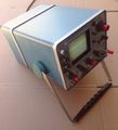
The Tektronix Type 422 is a 15 MHz portable dual-trace oscilloscope introduced in 1966. It was available with an optional battery back for operation without mains power.
Specifications
please add
The post-deflection acceleration voltage is 4900 V.
Internals
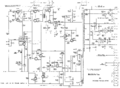
Early versions use an 8056 Nuvistor tube for the front-end cathode follower. Later versions use a FET front end. The 8056 Nuvistor used in the input amplifier of the 422 can be replaced by a MPF102 JFET.
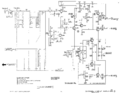
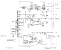
The trigger circuit in the 422 has a trigger amplifier driving a 1N3719 tunnel diode, D375, which acts as a Schmitt trigger. The trigger amplifier has a nonlinear deadband diode circuit in the negative feedback path. What results is high gain for small signals (little or no negative feedback) and low gain for large signals (strong negative feedback). Thus, the signal at the base of Q364 has a limited swing over a wide range of input amplitudes. The collector current of Q364 varies between 0 and 9 mA. Depending on the position of the trigger slope control, higher collector current in Q364 either switches D375 from the low-voltage state to the high-voltage state or from the high-voltage state to the low-voltage state. When D375 transitions from the low-voltage state to the high-voltage state, it produces a current pulse in the primary of transformer T401, which produces a current pulse in the secondary of T401. The secondary of T401 feeds another tunnel diode, D405, and the current pulse switches D405 to the high-voltage state, which starts a sweep.
The 422 uses the T4220 CRT.
Links
Pictures
External
-

-

-
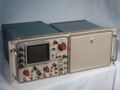
R422, compartment closed
-
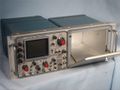
R422, compartment open
-
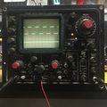
Black 422, panel mount
-
-
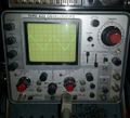
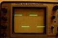
422 trace is sharp
-
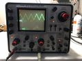
422 in ALT
-
-
-


Internal


Schematic
-
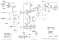
Trigger circuit
-
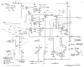
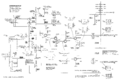
Sweep circuit
-
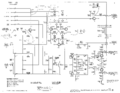
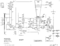
Vertical amplifier circuit
-
Input amplifier circuit
-
Horizontal amplifier circuit
-
CRT circuit
-
ac-dc power supply
-
ac power supply


