2247A: Difference between revisions
Jump to navigation
Jump to search
No edit summary |
m (→top: clean up, replaced: {{Oscilloscope Sidebar → {{Oscilloscope Sidebar |manufacturer=Tektronix |designers=, title=Tektronix → model=) |
||
| Line 1: | Line 1: | ||
{{Oscilloscope Sidebar | | {{Oscilloscope Sidebar |manufacturer=Tektronix |designers= | | ||
model= 2247A | | |||
summary=100 MHz portable 4-channel scope | | summary=100 MHz portable 4-channel scope | | ||
image=2247A.JPG | | image=2247A.JPG | | ||
Revision as of 06:51, 9 August 2021
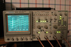
The Tektronix 2247A is a 100 MHz four-channel analog oscilloscope with a built-in 200 MHz counter/timer. (It is unknown if a 2247 non-A model was ever built.) Channels 1-2 are fully-functional, whereas 3-4 are limited in both deflection factor and coupling, as they are intended mainly for digital and trigger signals.
The 2247A includes the same features of the 2246 plus a Counter/Timer (C/T) integrated into the trigger system to provide many automated counting and timing measurements of frequency, period, width, totalize, frequency ratio, gated frequency, gated period, gated width, gated events, delta time, one-over-delta time, phase, rise/fall time, and propagation delay, using an internal or external freeuency standard.
Key Specifications
| Bandwidth | 100 MHz |
|---|---|
| Deflection | CH 1, CH 2: 2 mV/div to 5 V/div in 1-2-5 seq; CH 3, CH 4: 0.1 V/div and 0.5 V/div, all ±2%; BW Limit: 20 MHz ±15% |
| Vertical Operating Modes | CH1,2,3,4, CH2 Invert, Add, Alt, Chop (625 kHz) |
| Input Impedance | 1 MΩ ±1.0% // 20 pF ±1 pF |
| Maximum Input Voltage | 400 V (DC + peak AC) or 800 V (p-p ac at ≤ 10 kHz) |
| Sweep Speeds | A Time Base: 0.5 s/div to 20 ns/div in 1-2-5 seq; B Time Base: 5 ms/div to 20 ns/div in 1-2-5 seq (×10 magnifier to 2 ns/div) |
| Trigger | DC, Noise Reject, HF Reject, LF Reject, AC, TV Line, TV Field |
| Trigger Modes | A Mode: Auto Level, Auto, Norm, TV Line, TV Field, Single Seq. B Mode: Runs After Delay, Auto Level, Norm, TV Line (From A Source) |
| Trigger Source A & B | Vert, CH1, 2, 3, 4, Line |
| Voltmeter | DC, +Peak, −Peak, PK-PK, Gated Volts, Smart Tracking Cursors: Volts, Gnd, Trigger Lvl |
| Counter/Timer | Freq, Period, Width, Totalize, Freq Ratio, Sec, 1/Sec, Phase, Rise/Fall Time, Prop Delay Time |
| Cursors | Time, 1/Time, Delta Time, 1/Delta Time, Delta Phase, Volts |
| Interface | Ext Counter/Timer Base Input connector; Ext Z-Axis Input connector |
| Probes | Two P6109 100 MHz ×10 probes, BNC connector with a readout pin |
| Power | 100 W max, 90 − 250 VAC, 48 − 445 Hz |
Pictures
-
Front
-
-
-


