133: Difference between revisions
No edit summary |
No edit summary |
||
| Line 11: | Line 11: | ||
|designers= | |designers= | ||
|manuals= | |manuals= | ||
* [ | * [[Media:070-290.pdf|Tektronix 133 Manual]] (PDF) | ||
* [https://w140.com/tek_133_1968_catalog.pdf Tektronix 133 in 1968 Catalog (PDF) | * [https://w140.com/tek_133_1968_catalog.pdf Tektronix 133 in 1968 Catalog (PDF) | ||
}} | }} | ||
The '''Tektronix 133''' is an external enclosure and power supply for a [[letter-series_and_1-series_plug-ins|letter-series or 1-series plug-in]]. It was [[introduced in 1961]]. | The '''Tektronix 133''' is an external enclosure and power supply for a [[letter-series_and_1-series_plug-ins|letter-series or 1-series plug-in]]. It was [[introduced in 1961]]. | ||
Revision as of 08:27, 20 August 2021
The Tektronix 133 is an external enclosure and power supply for a letter-series or 1-series plug-in. It was introduced in 1961. The enclosure supplies power to the plug-in and the outputs from the plug-in are available. The bandwidth of the 133's outputs is 100 kHz, which is much slower than the 16 MHz bandwidth of the 132. However, the 133 has a 2 Ω output impedance compared to 5 kΩ for the 132, and the 133 can drive 1.5 amperes at its output, versus a maximum of 10 mA for the 132.
The signal path in the 133 starts with a differential pair of 2N398A PNP transistors (Q414 and Q424) amplifying the signal from the plug-in interface. The differential output of this first stage is used as two single-ended signals. One phase of the differential amplifier's output is sent to the MONITOR output connector. The other phase of the differential amplifier's output is sent to the high-current output amplifier. NORM/INV switch selects which output gets the inverting phase, and which gets the non-inverting phase.
The high-current output amplifier starts with a 2N1225 PNP (Q444) which functions as a feedback amplifier. The collector of Q444 drives the top and bottom halves of the push-pull output stage. The top side of the output stage is a Sziklai pair formed by a TI483 NPN (Q454) driving a 2N1905 PNP (Q474). The bottom side of the output stage is a TI483 NPN (Q463) driving a 2N1905 PNP (Q483). The output has a two ohm resistor and two ferrite beads in series.
Pictures
-
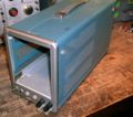
front view
-
front inside
-
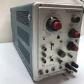
right view
-
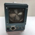
top view
-
left view shows power supply and TO-3 output power transistors
-
bottom view shows solid state rectifiers and capacitors for low-voltage high-current output amplifier
-
-
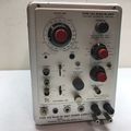
133 housing a 1A7
-
133 housing a 1A7
-
133 housing a 1A7
-
Power supply schematic
-
Plug-in connector and sync schematic
-
Amplifier schematic


