DM502: Difference between revisions
No edit summary |
mNo edit summary |
||
| Line 2: | Line 2: | ||
designers= |manuals= | designers= |manuals= | ||
* [[Media:070-1726-00.pdf|Tektronix DM502 Manual]] | * [[Media:070-1726-00.pdf|Tektronix DM502 Manual]] | ||
* [[Media:070-2693-00.pdf|Tektronix DM502A Manual]] ( | * [[Media:070-2693-00.pdf|Tektronix DM502A Manual]] (OCR) | ||
}} | }} | ||
It has an Int/Ext switch that allows alternate input connections via the rear interface to be selected. | It has an Int/Ext switch that allows alternate input connections via the rear interface to be selected. | ||
The DM502 is available with an input for temperature measurement with a transistor temperature probe ([[P6430]]) | The DM502 is available with an input for temperature measurement with a transistor temperature probe ([[P6430]]) using an NPN transistor, e.g. a 2N2484 (any NPN-Transistor with h<sub>FE</sub> >150 can be used). | ||
using an NPN transistor, e.g. a 2N2484 (any NPN-Transistor with h<sub>FE</sub> >150 can be used). | |||
The DM502'''A''' model adds an input for a PT-100 temperature probe ([[P6601]]), a True RMS converter, | The DM502'''A''' model adds an input for a PT-100 temperature probe ([[P6601]]), | ||
and offset circuits to read dB directly in all ranges. An "Option 2" instrument deletes the temperature | a True RMS converter, and offset circuits to read dB directly in all ranges. | ||
measurement function, P6601 temperature probe, and all internal circuits associated with this function. | An "Option 2" instrument deletes the temperature measurement function, P6601 temperature probe, | ||
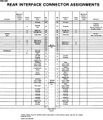
The rear interface of DM502'''A''' is limited compared to the DM502: No current input and no reading output, see gallery below. | and all internal circuits associated with this function. | ||
The rear interface of DM502'''A''' is limited compared to the DM502: | |||
No current input and no reading output, see gallery below. | |||
The 2 kΩ measurement range (+HI in DM502A) can be used for diode testing, since a current source of 1 mA is active | The 2 kΩ measurement range (+HI in DM502A) can be used for diode testing, since | ||
and the reading corresponds to the (forward) voltage drop of the diode in Volts. The voltage can rise to a maximum of 10 V. | a current source of 1 mA is active and the reading corresponds to the (forward) | ||
voltage drop of the diode in Volts. The voltage can rise to a maximum of 10 V. | |||
A second voltmeter is needed to measure the voltage if 2 V are exceeded. | A second voltmeter is needed to measure the voltage if 2 V are exceeded. | ||
| Line 35: | Line 37: | ||
Tek dm502 front.jpg | Tek dm502 front.jpg | ||
Tek dm502 left.jpg | Tek dm502 left.jpg | ||
DM502_switch_inside.jpg|DM502 switch with cover off. The cover removes easily using | DM502_switch_inside.jpg|DM502 switch with cover off. The cover removes easily using a Pozidrive screwdriver. | ||
Tek dm502 right.jpg | Tek dm502 right.jpg | ||
Tek dm502 leftfront.jpg | Tek dm502 leftfront.jpg | ||
Revision as of 01:37, 15 October 2022
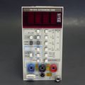
The Tektronix DM502 is a basic 3½ digit digital multimeter plug-in for the TM500 system.
It has an Int/Ext switch that allows alternate input connections via the rear interface to be selected.
The DM502 is available with an input for temperature measurement with a transistor temperature probe (P6430) using an NPN transistor, e.g. a 2N2484 (any NPN-Transistor with hFE >150 can be used).
The DM502A model adds an input for a PT-100 temperature probe (P6601), a True RMS converter, and offset circuits to read dB directly in all ranges. An "Option 2" instrument deletes the temperature measurement function, P6601 temperature probe, and all internal circuits associated with this function. The rear interface of DM502A is limited compared to the DM502: No current input and no reading output, see gallery below.
The 2 kΩ measurement range (+HI in DM502A) can be used for diode testing, since a current source of 1 mA is active and the reading corresponds to the (forward) voltage drop of the diode in Volts. The voltage can rise to a maximum of 10 V. A second voltmeter is needed to measure the voltage if 2 V are exceeded.
Key Specifications
| Voltage ranges | 200 mV to 200 V in decade steps; 1 kV (DC) / 500 V (AC) top range |
|---|---|
| Input impedance DM502 | 10 MΩ or direct JFET input >2 GΩ (by internal jumper) |
| Input impedance DM502A | 10 MΩ |
| Current ranges | 200 μA to 2 A in decade steps |
| Resistance ranges | 200 Ω to 20 MΩ in decade steps |
Links
- Tektronix DM502 Multimeter Repair by NFM @ YouTube
Pictures
DM502
-
-
-
-
DM502 switch with cover off. The cover removes easily using a Pozidrive screwdriver.
-
-
-
-
-
-
DM502 rear interface
DM502A
-
-
-
-
DM502A right internal
-
DM502A rear interface


