7A22: Difference between revisions
No edit summary |
No edit summary |
||
| Line 1: | Line 1: | ||
{{Plugin Sidebar| | |||
title=Tektronix 7A22| | |||
summary=1 MHz differential amplifier| | |||
image=tek-7a22-front.jpg | | |||
caption=7A22 front view| | |||
years=1969 – 2000 | | |||
type=Vertical Amplifier| | |||
series=[[7000-series scopes]]| | |||
manuals= | |||
* [http://bama.edebris.com/download/tek/7a22(2)/tek-7a22.pdf Tektronix 7A22 Manual (PDF)] | |||
* [http://w140.com/smb/7a22_sm.pdf Tektronix 7A22 Manual (OCR, PDF)] | |||
}} | |||
The 7A22 is a single channel differential vertical amplifier for the 7000 series mainframes, produced from about 1969 to 2000. | The 7A22 is a single channel differential vertical amplifier for the 7000 series mainframes, produced from about 1969 to 2000. | ||
| Line 7: | Line 19: | ||
An example application is found in Jim Williams' [http://cds.linear.com/docs/en/application-note/an124f.pdf Application Note 124] – see Appendix D for a comparison of differential amplifiers. | An example application is found in Jim Williams' [http://cds.linear.com/docs/en/application-note/an124f.pdf Application Note 124] – see Appendix D for a comparison of differential amplifiers. | ||
== | ==Specifications== | ||
==Pictures== | ==Pictures== | ||
<gallery> | <gallery> | ||
Image:tri-1000k_w.jpg | 7A22: 1 kHz, 130 μV<sub>p-p</sub> triangle signal, BW=1 MHz | Image:tri-1000k_w.jpg | 7A22: 1 kHz, 130 μV<sub>p-p</sub> triangle signal, BW=1 MHz | ||
Image:tri-100k_w.jpg | 7A22: 1 kHz, 130 μV<sub>p-p</sub> triangle signal, BW=100 kHz | Image:tri-100k_w.jpg | 7A22: 1 kHz, 130 μV<sub>p-p</sub> triangle signal, BW=100 kHz | ||
| Line 23: | Line 31: | ||
[[Category:7000 series vertical plugins]] | [[Category:7000 series vertical plugins]] | ||
[[Category:Specifications needed]] | |||
Revision as of 06:21, 6 May 2014

The 7A22 is a single channel differential vertical amplifier for the 7000 series mainframes, produced from about 1969 to 2000.
Remarkably, the 7A22's input sensitivity reaches down to 10 μV/div. Bandwidth is 1 MHz, the upper 3dB limit can be reduced in ×3 steps down to 100 Hz (to eliminate noise, inter alia), and the lower bandwidth can be raised in ×10 steps from 0.1 Hz to 10 kHz. A separate control optionally supplies an internal DC voltage to offset the DC signal component. Even in the most sensitive ranges (10 μV/div to 10 mV/div), common-mode voltage can be ±10 V. Input resistance is 1 MΩ but for high source resistance DC coupled measurements, one can disconnect the internal gate return resistors of the input FETs, at the cost of disabling the 20mv/div and higher ranges.
Applications include audio, biological signals, etc.
An example application is found in Jim Williams' Application Note 124 – see Appendix D for a comparison of differential amplifiers.
Specifications
Pictures
-
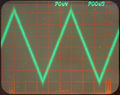
7A22: 1 kHz, 130 μVp-p triangle signal, BW=1 MHz
-
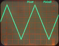
7A22: 1 kHz, 130 μVp-p triangle signal, BW=100 kHz
-
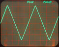
7A22: 1 kHz, 130 μVp-p triangle signal, BW=10 kHz
-
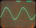
7A22: 1 kHz, 130 μVp-p triangle signal, BW=1 kHz


