7A22: Difference between revisions
No edit summary |
No edit summary |
||
| Line 24: | Line 24: | ||
* Deflection: 10 μV/Div to 10 V/Div in 1–2–5 sequence | * Deflection: 10 μV/Div to 10 V/Div in 1–2–5 sequence | ||
* Input impedance (either input): 1 MΩ || 47 pF | * Input impedance (either input): 1 MΩ || 47 pF | ||
{| border=1 | | |||
!Range | |||
! Differential signal | |||
! DC Offset | |||
! Common mode | |||
|- | |||
| 10 μV/Div to 10 mV/Div || ±1 V || ±1 V || ±10 V | |||
|- | |||
| 20 mV/Div to 0.1 V/Div || ±10 V || ±10 V || ±100 V | |||
|- | |||
| 0.2 V/Div to 1 V/Div || ±100 V || ±100 V || ±500 V | |||
|- | |||
| 2 V/Div to 10 V/Div || ±1000 V || ±1000 V || ±500 V | |||
|- | |||
|} | |||
==Pictures== | ==Pictures== | ||
Revision as of 06:40, 11 May 2014

The 7A22 is a single channel differential vertical amplifier for the 7000 series mainframes, produced from about 1969 to 2000. Specifications and controls are similar to the 26A2 and the 3A9 from the 560 series but without current probe input or front panel signal output.
Remarkably, the 7A22's input sensitivity reaches down to 10 μV/Div. Bandwidth is 1 MHz, the upper 3 dB limit can be reduced in ×3 steps down to 100 Hz (to eliminate noise, inter alia), and the lower bandwidth can be raised in ×10 steps from 0.1 Hz to 10 kHz. A separate control optionally supplies an internal DC voltage to offset the DC signal component. Even in the most sensitive ranges (10 μV/Div to 10 mV/Div), common-mode voltage can be ±10 V. Input resistance is 1 MΩ, but for high source resistance DC coupled measurements, one can disconnect the internal gate return resistors of the input FETs, at the disadvantage of disabling the 20 mV/div and higher ranges.
Applications include audio, biological signals, etc.
An example application is found in Jim Williams' Application Note 124 – see Appendix D for a comparison of differential amplifiers.
Specifications
- Bandwidth: 1 MHz, LF limit switchable DC, 0.1 Hz to 10 kHz in ×10 steps, HF limit switchable 100 Hz to 1 MHz in ×3/×10 steps
- Deflection: 10 μV/Div to 10 V/Div in 1–2–5 sequence
- Input impedance (either input): 1 MΩ || 47 pF
| Range | Differential signal | DC Offset | Common mode |
|---|---|---|---|
| 10 μV/Div to 10 mV/Div | ±1 V | ±1 V | ±10 V |
| 20 mV/Div to 0.1 V/Div | ±10 V | ±10 V | ±100 V |
| 0.2 V/Div to 1 V/Div | ±100 V | ±100 V | ±500 V |
| 2 V/Div to 10 V/Div | ±1000 V | ±1000 V | ±500 V |
Pictures
-
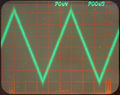
7A22: 1 kHz, 130 μVp-p triangle, BW=1 MHz
-
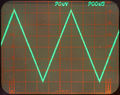
7A22: 1 kHz, 130 μVp-p triangle, BW=100 kHz
-
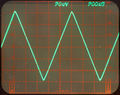
7A22: 1 kHz, 130 μVp-p triangle, BW=10 kHz
-
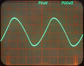
7A22: 1 kHz, 130 μVp-p triangle, BW=1 kHz
-
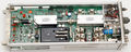
left side
-

left side (with cover)
-
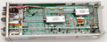
right side


