P6460: Difference between revisions
Jump to navigation
Jump to search
No edit summary |
No edit summary |
||
| Line 13: | Line 13: | ||
* [[Media:Tek p6460 missing first two pages no ocr.pdf|P6460 Instruction Manual, July 1986 Update]] (incomplete, OCR) | * [[Media:Tek p6460 missing first two pages no ocr.pdf|P6460 Instruction Manual, July 1986 Update]] (incomplete, OCR) | ||
}} | }} | ||
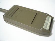
The '''Tektronix P6460''' Data Acquisition Probe may be used with [[DAS9100]], [[91A24]], [[91AE24]], [[1240D1]], or [[1240D2]] Logic Analyzers. It may also be used with and is required for the [[DP100]] Digital Video Probe plug-in used in the TM500 mainframes. It provides 8 data channels plus one qualifier and one clock channel. | The '''Tektronix P6460''' Data Acquisition Probe may be used with [[DAS9100]], [[91A24]], [[91AE24]], [[91S16]], [[1240D1]], or [[1240D2]] Logic Analyzers. It may also be used with and is required for the [[DP100]] Digital Video Probe plug-in used in the TM500 mainframes. It provides 8 data channels plus one qualifier and one clock channel. | ||
The P6460 uses the [[P64xx input leads|P64xx-family 10-wire input lead harnesses]] with 0.2" connectors. Is also possible to use standard jumper wires with pins, sockets or clips on the other end for connecting inputs. | The P6460 uses the [[P64xx input leads|P64xx-family 10-wire input lead harnesses]] with 0.2" connectors. Is also possible to use standard jumper wires with pins, sockets or clips on the other end for connecting inputs. | ||
Latest revision as of 05:38, 12 December 2024
The Tektronix P6460 Data Acquisition Probe may be used with DAS9100, 91A24, 91AE24, 91S16, 1240D1, or 1240D2 Logic Analyzers. It may also be used with and is required for the DP100 Digital Video Probe plug-in used in the TM500 mainframes. It provides 8 data channels plus one qualifier and one clock channel.
The P6460 uses the P64xx-family 10-wire input lead harnesses with 0.2" connectors. Is also possible to use standard jumper wires with pins, sockets or clips on the other end for connecting inputs.
Key Specifications
| Maximum Clock Frequency | ? |
|---|---|
| Data channel Bandwidth | 100 MHz |
| Minimum Pulse Width | 4 ns |
| Input Signal Level | -40 V to +10 V above threshold (+30 V for RS232) |
| Threshold Voltage | provided from Logic Analyzer |
| Input Capacitance | 5 pF |
| Non-destructive Input Voltage Range | ±40 V |
| Maximum Voltage between any two Inputs | ±60 V |


