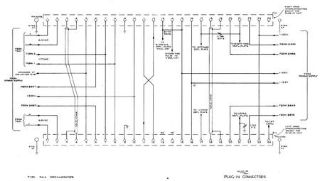
560 Series plug-in interface
The plug-in interface of the 560-series scopes is a single 24-pin Amphenol connector per slot (horizontal/vertical).

| Pin | Function | Comment |
|---|---|---|
| 1 | 6.3 VAC | 6 A capacity in 561, dedicated winding per slot |
| 2 | 6.3 VAC | return for pin 1 |
| 3 | plug-in interconnect | 50 Ω coax between slots, center conductor on right slot, screen on left slot |
| 4 | plug-in interconnect | 50 Ω coax between slots, screen on right slot, center conductor on left slot |
| 5 | ground return to PSU | |
| 6 | +420 V unreg. via 2 kΩ | from +300 V regulator input |
| 7 | 117 VAC | from mains transformer primary (power line) |
| 8 | 117 VAC | return for pin 8 |
| 9 | chassis ground | |
| 10 | +300 V reg. | |
| 11 | trigger signal out (V) | to pin 12 on other slot |
| 12 | trigger signal in (H) | from pin 11 on other slot |
| 13 | blanking | to blanking deflection plate on CRT, 560 kΩ pull-up to 125 V in 561 (NC on left slot) |
| 14 | intensifying | to CRT (NC on left slot) |
| 15 | +125 V reg. | |
| 16 | −12.2 V reg. | |
| 17 | −deflection plate | left H on right slot, lower V on left slot |
| 18 | plug-in interconnect | 50 Ω coax between slots, center conductor |
| 19 | plug-in interconnect | 50 Ω coax between slots, screen |
| 20 | +210 V unreg. via 2 kΩ | from +125 V regulator input |
| 21 | +deflection plate | right H on right slot, upper V on left slot |
| 22 | +75 V unreg. via 2 kΩ | from −100 V regulator input |
| 23 | −100 V reg. | |
| 24 | CRT cathode | NC on right slot; grounded by amplifiers, NC in timebases |
Pin group function legend
DC power AC and heater power Deflection and Trigger Signals Control Signals