190: Difference between revisions
No edit summary |
No edit summary |
||
| Line 1: | Line 1: | ||
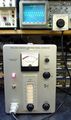
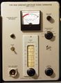
The '''Tektronix Type 190A and 190B Constant-Amplitude Signal Generator''' is a | {{Instrument Sidebar | ||
sine wave source that uses feedback to provide a signal whose amplitude | |manufacturer=Tektronix | ||
does not vary with frequency or with the impedance of the load, within | |model=190 | ||
stated limits | |class=Signal Generator | ||
|series= | |||
|summary=Constant-Amplitude Signal Generator | |||
|image=Tek 190b front.jpg | |||
|caption=Tek 190B front | |||
|introduced=1954 | |||
|discontinued=(?) | |||
|designers= | |||
|manuals= | |||
* [[Media:070-413.pdf|Tektronix 190A/190B Manual (PDF)]] | |||
* [[Media:Tek 190 distortion meter.pdf|Distortion Measurement Fixture for Tektronix 190 (PDF, needs OCR)]] | |||
* [[Media:50MHz to 100MHz stoll march 1959.pdf|Generating 100 MHz from 50 MHz Output of 190 or TU-50]] | |||
* [https://w140.com/tek_fcp/tek_type_190_a_b_factory_cal_proc.pdf Tektronix 190 Factory Calibration Procedure (PDF)] | |||
<!-- * [http://bama.edebris.com/download/tek/190/190.djvu Tektronix 190 Manual (DjVu)] --> | |||
}} | |||
The '''Tektronix Type 190A and 190B Constant-Amplitude Signal Generator''' is a sine wave source that uses feedback to provide a signal whose amplitude does not vary with frequency or with the impedance of the load, within stated limits. | |||
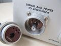
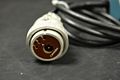
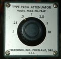
The | The frequency range is 350 kHz to 50 MHz. The amplitude measurement is made using a peak-to-peak (envelope) detector in an external attenuator head that is connected to the main unit by a special cable. | ||
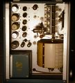
The 190A uses a [[6110]] double diode tube for the detector. The 190B uses two [[1N87A]] germanium diodes for the detector. | |||
to the | |||
The oscillation frequency of the 190B is controlled | The 190 is useful for measuring the frequency response of a device whose input impedance varies with frequency. | ||
by a rotary variable capacitor. | If a standard 50-ohm signal generator is used for this purpose, the frequency-domain variations of the input impedance of the device under test will result in frequency-domain variations in the actual signal voltage that is applied to the input. | ||
The variable capacitor rotates together with a drum | This interaction between is input impedance and gain measurements is often undesirable. Having a constant-amplitude source simplifies the measurement. | ||
that serves as the frequency readout dial. | |||
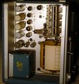
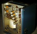
The drum is made of cream colored plastic | The oscillation frequency of the 190B is controlled by a rotary variable capacitor. | ||
and has a diameter of 5" (12. | The variable capacitor rotates together with a drum that serves as the frequency readout dial. | ||
The frequency knob on the front panel of the 190B | The drum is made of cream colored plastic and has a diameter of 5" (12.5 cm) and a height of 4" (10 cm). | ||
turns a rubber wheel which, by friction, turns the drum. | The frequency knob on the front panel of the 190B turns a rubber wheel which, by friction, turns the drum. | ||
The relatively large diameter of the drum provides for | The relatively large diameter of the drum provides for precise frequency control, long effective length of the readout dial, and ensures that the friction coupling between the frequency knob and the drum provides sufficient torque to turn the drum and rotary capacitor without any slippage. | ||
precise frequency control, | |||
long effective length of the readout dial, and | |||
ensures that the friction coupling between the frequency knob and the drum | |||
provides sufficient torque to turn the drum and rotary capacitor without any slippage. | |||
The [[067-0041-00]] modification kit extends the low-frequency range of the 190A. | The [[067-0041-00]] modification kit extends the low-frequency range of the 190A. | ||
==Pictures== | |||
<gallery> | <gallery> | ||
Tek 190b front.jpg|190B | Tek 190b front.jpg|190B | ||
Revision as of 04:08, 18 August 2021

The Tektronix Type 190A and 190B Constant-Amplitude Signal Generator is a sine wave source that uses feedback to provide a signal whose amplitude does not vary with frequency or with the impedance of the load, within stated limits.
The frequency range is 350 kHz to 50 MHz. The amplitude measurement is made using a peak-to-peak (envelope) detector in an external attenuator head that is connected to the main unit by a special cable. The 190A uses a 6110 double diode tube for the detector. The 190B uses two 1N87A germanium diodes for the detector.
The 190 is useful for measuring the frequency response of a device whose input impedance varies with frequency. If a standard 50-ohm signal generator is used for this purpose, the frequency-domain variations of the input impedance of the device under test will result in frequency-domain variations in the actual signal voltage that is applied to the input. This interaction between is input impedance and gain measurements is often undesirable. Having a constant-amplitude source simplifies the measurement.
The oscillation frequency of the 190B is controlled by a rotary variable capacitor. The variable capacitor rotates together with a drum that serves as the frequency readout dial. The drum is made of cream colored plastic and has a diameter of 5" (12.5 cm) and a height of 4" (10 cm). The frequency knob on the front panel of the 190B turns a rubber wheel which, by friction, turns the drum. The relatively large diameter of the drum provides for precise frequency control, long effective length of the readout dial, and ensures that the friction coupling between the frequency knob and the drum provides sufficient torque to turn the drum and rotary capacitor without any slippage.
The 067-0041-00 modification kit extends the low-frequency range of the 190A.
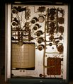
Pictures
-
190B
-
190B
-
190B
-
190B
-
190B
-

Rubber wheel rotating frequency drum in 190B
-

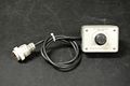
190B attenuator
-
190B attenuator
-
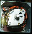
190A Attenuator Internal View
-
attenuator connector
-
190B attenuator connector
-
190A Attenuator Front View
-

-