555

The Tektronix Type 555 is a dual-beam CRT oscilloscope introduced by Tektronix in
1959 and made until the late 1960's, when it was replaced
by the 556.
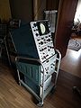
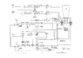
The system is split across two pieces: the main indicator unit
and the external power supply unit.
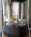
The power supply unit contains the main transformer,
rectifiers and regulators for all of the voltages
except the filament and CRT HV supplies.
The filament and CRT HV voltages are generated in the 555 indicator unit.
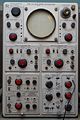
The Tektronix 555 takes two letter-series or 1-series vertical plug-ins
Type 21 and 22 Timebases
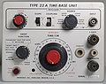
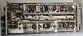
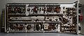
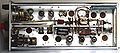
The 555 uses special horizontal plug-ins that contain the trigger and sweep. Early instances of the 555 came with the 21 and 22 horizontal plug-ins. A rigid plug-in extension for the timebases (part number 013-013) was included with every 555.
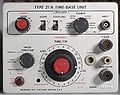
Type 21A and 22A Timebases
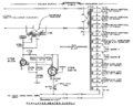
Later instances came with the 21A and 22A horizontal plug-ins, which use tunnel diodes for triggering. Delayed triggering is supported. Since the 555 is a dual-beam scope, it is also possible to start one of the sweeps while the other beam is sweeping. The upper-beam sweep and lower-beam sweeps are, in fact, totally independent.
Filament Supply Regulator
Regulation of the filament supply happens as follows: There is a feedback loop that is formed between the indicator unit and the power supply unit. The power supply sends AC through the interconnection cable to the indicator unit, where it is connected to the primary of the filament transformer. A sample of the output of the filament transformer is sent back through the interconnection cable (part number 012-032) from the indicator unit to the power supply unit. This performs two functions. First, the filament voltage that is sent back to the power supply unit is used to heat the cathodes of tubes in the power supply unit. Second, this filament voltage is the feedback signal to a regulator in the power supply unit that controls how much voltage is sent to the filament transformer. One of the consequences of this scheme is that it is impossible to energize the power supply unit without the indicator unit connected. The regulator tubes in the power supply would remain cold without filament power, and would not pass any current.
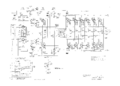
Vertical Amplifier
The Tektronix 555 has a six-section differential distributed vertical output amplifier made of 6DK6 tubes. It is the same as the vertical output amplifier in the 551 and the 545A. An L-C delay line is between the vertical output amplifier and the CRT vertical deflection plates for each channel.
Architecturally, the 555, with its four plug-ins, is similar to the 7844.
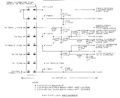
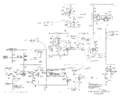
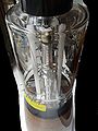
CRT Circuit
The CRT circuit in the 555 has two high voltage transformers. One transformer, T901, generates:
- CRT anode voltage: +8650V
- lower beam CRT cathode voltage: -1350V
- lower beam CRT control grid (blanking) voltage: floating, -1500V
The other transformer, T801, generates:
- upper beam CRT cathode voltage: -1350V
- upper beam CRT control grid (blanking) voltage: floating, -1500V
Pictures
-
-
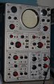
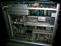
front view: two timing plug-ins on top and two vertical plug-ins on bottom
-
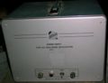
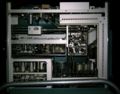
external power supply
-
left side view
-
right side view
-
top view
-

555 with P11-option
-
555 with P7-option (fast blue and slow green Phosphor)
-
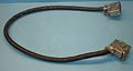
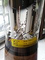
Power interconnect, part number 012-032
-
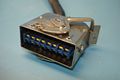
Power interconnect, part number 012-032
-
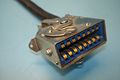
Power interconnect, part number 012-032
-
timebase interconnect
-
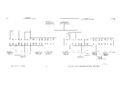
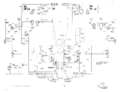
555 block diagram
-
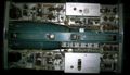
lower beam vertical amplifier
-
power interconnect
-
heater regulator
-
Type 21 trigger
-
block diagram
-
CRT circuit
-
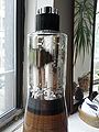
CRT
-
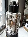
CRT
-
CRT
-
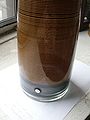
CRT
-
CRT
-
CRT
-
22A front
-
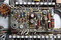
22A TD trigger board
-

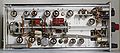
22A top
-
22A bottom
-
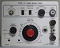
21 front
-
21 top
-

21 bottom
-

22 front
-
22 top
-
22 bottom
-
21A front
-

21A top
-
21 bottom
-
21A TD trigger board
-
timebase plug-in extender, part number 013-013
-

-