551

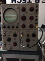
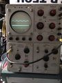
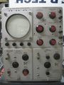
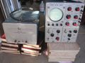
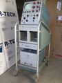
The Tektronix Type 551, introduced in 1958, is a 27 MHz dual-beam scope that takes two letter-series and 1-series plug-ins.
Unlike the 555, it has only one set of horizontal deflection plates and the trigger and sweep circuitry are built in to the mainframe. The vertical amplifiers of the 545A, 551, and 555 are identical. The 551 uses an L-C delay line for each vertical channel.
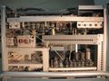
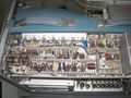
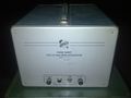
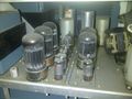
Like the 555, the 551 has two parts, the "indicator unit" containing the signal path electronics and CRT, and an external power supply unit. The external power supplies of the 555 and 551 are not interchangeable, however, the cable that connects the power supply to the indicator unit (part number 012-032) is the same for the 551 and the 555.
The filament current for the tubes in the indicator unit is produced by a transformer in the indicator unit, T750 (part number 120-235), that has seven isolated secondaries, each supplying 6.3 VAC. The indicator unit also contains the CRT circuit, which uses 5642 tubes and produces the +8650 V CRT anode voltage and the −1350 V voltage for the CRT cathode. The external power supply unit produces regulated DC voltages of −150 V, +100 V, +225 V, +350 V, and +500 V.
A factory modification, MOD 108A, was available for increasing the CRT acceleration voltage from 10 kV to 12 kV to improve trace visibility at high sweep rates, at the cost of reducing deflection sensitivity to 0.85 cm/Div. A graticule with 0.85 cm units was supplied.
Early 551 units used UHF connectors. Many were converted in the field to use BNC connectors.
Key Specifications
| CRT | T57 (T551) in early, T5511 in later (SN 2032+) models |
|---|
| 551 | 555 | |
|---|---|---|
| Rise time with Type K | 14 ns | 12 ns |
| Acceleration Voltage | 10 kV | 10 kV |
| Filament Regulation | none | saturable core reactor |
| Price in 1965 (2015 equiv.) |
$1,850 ($14,000) |
$2,650 ($20,100) |
| Indicator Weight | 52 lb (23.6 kg) | 68 lb (30.8 kg) |
| Power Supply Weight | 42 lb (19 kg) | 45 lb (20.4 kg) |
| Power Consumption | 850 W | 1050 W |
Links
Pictures
-
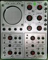
Front view
-
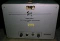
External power supply
-
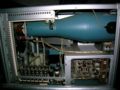
Left side.
-
Right side.
-
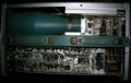
Top view.
-
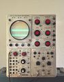
front view.
-
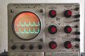
front view closeup.
-
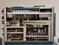
Left side.
-
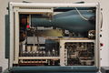
Right side.
-
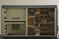
Bottom.
-
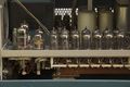
lower beam distributed amplifier.
-
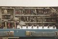
Timebase & calibration adjustments.
-
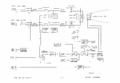
Block diagram
-
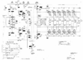
Vertical amplifier
-

Horizontal amplifier
-
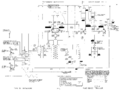
trigger schematic
-
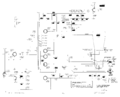
CRT circuit
-
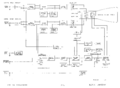
block diagram
-
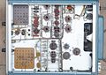
bottom of power supply
-
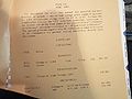
Tek 551 Mod 108A
-

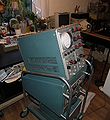
551 with Mod 108A
-
-
-
-
-

-
-
-
-
-
-
-
-
power supply
-
power supply


