DC502: Difference between revisions
Jump to navigation
Jump to search
m (→top: clean up, replaced: manuals= → designers= |manuals=) |
No edit summary |
||
| Line 1: | Line 1: | ||
{{TM500 | mfg=Tektronix | type=DC502 | function=550 MHz frequency counter | class=counter | image=Tek dc502 opt1 1.jpg | introduced=1972 | discontinued=1977 | designers= |manuals= | {{TM500 | mfg=Tektronix | type=DC502 | function=550 MHz frequency counter | class=counter | image=Tek dc502 opt1 1.jpg | introduced=1972 | discontinued=1977 | designers= |manuals= | ||
* [[Media:DC502 070-1412-00.pdf|Tektronix DC502 Manual | * [[Media:DC502 070-1412-00.pdf|Tektronix DC502 Manual]] | ||
}} | }} | ||
It measures frequencies from 10 Hz to 550 MHz or totalizes events up to the readout capacity of 10<sup>7</sup> | It measures frequencies from 10 Hz to 550 MHz or totalizes events up to the readout capacity of 10<sup>7</sup>−1 at the maximum rate of 550 MHz. | ||
{{BeginSpecs}} | |||
{{Spec|Resolution|7 digits}} | |||
{{Spec|Frequency range | 10 Hz to 110 MHz (Direct input); 50 MHz to 550 MHz (÷10 input) }} | |||
{{Spec|Sensitivity|300 mV<sub>p-p</sub> or 100 mV<sub>rms</sub> sine (Direct input); 500 mV<sub>p-p</sub> or 170 mV<sub>rms</sub> sine (÷10 input) }} | |||
{{Spec|Input impedance| 1 MΩ (Direct input); 50 Ω (÷10 input) }} | |||
{{Spec|Gate time| 0.01 s, 0.1 s, 1.0 s, or 10 s }} | |||
{{Spec|Stability|1×10<sup>−5</sup> (10 ppm) standard, 5×10<sup>−7</sup> (0.5 ppm) with Opt.01}} | |||
{{Spec|Features| | |||
* 7-digit LED Display, automatic decimal point and leading zero blanking | |||
* manual Start/Stop (Totalize) | |||
* adjustable trigger level on direct input | |||
}} | |||
{{EndSpecs}} | |||
The manual totalizing mode with front panel start stop control is available in both inputs; from the prescale input, 1 displayed count per 10 input events will result. | The manual totalizing mode with front panel start stop control is available in both inputs; from the prescale input, 1 displayed count per 10 input events will result. | ||
LEDs indicate when the gate is armed, and whether displayed numbers are in kHz or MHz, and when register overflow occurs. | LEDs indicate when the gate is armed, and whether displayed numbers are in kHz or MHz, and when register overflow occurs. | ||
The internal clock is 1 MHz. The Opt.05 high stability oscillator runs at 5 MHz with an additional by-5 divider. | |||
==Links== | ==Links== | ||
* [http://www.barrytech.com/tektronix/tektm500/tekdc502.html DC502 @ barrytech.com] | * [http://www.barrytech.com/tektronix/tektm500/tekdc502.html DC502 @ barrytech.com] | ||
==Rear Interface== | |||
{| class="wikitable" | |||
|- | |||
! Connector Pin | |||
! Signal | |||
|- | |||
| 28B || Second decimal point output | |||
|- | |||
| 27B || MHz light output | |||
|- | |||
| 27A || Internal Scan Clock Disable | |||
|- | |||
| 26A || /RESET | |||
|- | |||
| 25B || External Scan Clock input | |||
|- | |||
| 25A || Time Slot Zero | |||
|- | |||
| 24B || Internal Scan Clock output (2 kHz) | |||
|- | |||
| 23B || Overflow | |||
|- | |||
| 22B || MSD output | |||
|- | |||
| 21B || BCD output 2 | |||
|- | |||
| 20B || BCD output 8 | |||
|- | |||
| 20A || BCD output 4 | |||
|- | |||
| 19A || BCD output 1 | |||
|- | |||
| 19B || Data Good | |||
|} | |||
Data is output serially by digit. | |||
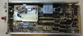
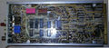
==Pictures== | ==Pictures== | ||
Revision as of 07:32, 10 July 2022

The Tektronix DC502 is a 550 MHz frequency counter plug-in for the TM500 system.
It measures frequencies from 10 Hz to 550 MHz or totalizes events up to the readout capacity of 107−1 at the maximum rate of 550 MHz.
Key Specifications
| Resolution | 7 digits |
|---|---|
| Frequency range | 10 Hz to 110 MHz (Direct input); 50 MHz to 550 MHz (÷10 input) |
| Sensitivity | 300 mVp-p or 100 mVrms sine (Direct input); 500 mVp-p or 170 mVrms sine (÷10 input) |
| Input impedance | 1 MΩ (Direct input); 50 Ω (÷10 input) |
| Gate time | 0.01 s, 0.1 s, 1.0 s, or 10 s |
| Stability | 1×10⁻⁵ (10 ppm) standard, 5×10⁻⁷ (0.5 ppm) with Opt.01 |
| Features |
|
The manual totalizing mode with front panel start stop control is available in both inputs; from the prescale input, 1 displayed count per 10 input events will result.
LEDs indicate when the gate is armed, and whether displayed numbers are in kHz or MHz, and when register overflow occurs.
The internal clock is 1 MHz. The Opt.05 high stability oscillator runs at 5 MHz with an additional by-5 divider.
Links
Rear Interface
| Connector Pin | Signal |
|---|---|
| 28B | Second decimal point output |
| 27B | MHz light output |
| 27A | Internal Scan Clock Disable |
| 26A | /RESET |
| 25B | External Scan Clock input |
| 25A | Time Slot Zero |
| 24B | Internal Scan Clock output (2 kHz) |
| 23B | Overflow |
| 22B | MSD output |
| 21B | BCD output 2 |
| 20B | BCD output 8 |
| 20A | BCD output 4 |
| 19A | BCD output 1 |
| 19B | Data Good |
Data is output serially by digit.
Pictures
-

-
-
-
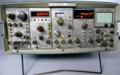
DC502 in TM515 with other TM500 gear


