DL2: Difference between revisions
Jump to navigation
Jump to search
No edit summary |
No edit summary |
||
| (One intermediate revision by the same user not shown) | |||
| Line 26: | Line 26: | ||
==Links== | ==Links== | ||
* [http://www.barrytech.com/tektronix/tek7000/tekdl2.html DL2 @ barrytech.com] | * [http://www.barrytech.com/tektronix/tek7000/tekdl2.html DL2 @ barrytech.com] | ||
* [ | * [https://www.amplifier.cd/Test_Equipment/Tektronix/Tektronix_7000_series_special/logicanalyzer_7D01.htm 7D01, DF1, DF2 and DL2 @ amplifier.cd] | ||
{{Documents|Link=DL2}} | |||
==Pictures== | ==Pictures== | ||
| Line 41: | Line 42: | ||
</gallery> | </gallery> | ||
{{ | ==Components== | ||
{{Parts|DL2}} | |||
[[Category:7000 series special-function plugins]] | [[Category:7000 series special-function plugins]] | ||
[[Category:Logic analyzers]] | [[Category:Logic analyzers]] | ||
Latest revision as of 06:42, 12 December 2023

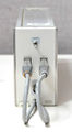
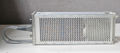
The Tektronix DL2 Digital Latch is a plug-in for 7000-series scopes that functions as a glitch detector extension to the 7D01 logic analyzer. There is a TM500 counterpart, the DL502.
It connects between the P6451 probes and the 7D01 and receives the latter's store clock via a front panel BNC connector. Short pulses ≥5 ns are stretched to the clock period.
Key Specifications
| Number of channels | 16 |
|---|---|
| Minimum pulse width | 5 ns |
| Minimum clock period | 20 ns |
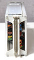
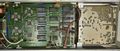
Internals
The data path in the DL2 is built using standard 100k ECL circuits. The –4.8 V and –2 V ECL supplies are generated by a 555-driven switcher powered off the ±15 V rails (same board as in the 7D01).
Links
Documents Referencing DL2
| Document | Class | Title | Authors | Year | Links |
|---|---|---|---|---|---|
| Tekscope 1977 V9 N3.pdf | Article | New Products | 1977 | FEM181 • DL2 • DL502 • 851 |
Pictures
-
-
-
-
-
-

-
-
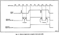
Operating principle (timing diagram)
-
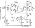
Operating principle (channel schematic)


Components
Some Parts Used in the DL2