DP501: Difference between revisions
No edit summary |
No edit summary |
||
| (9 intermediate revisions by 3 users not shown) | |||
| Line 1: | Line 1: | ||
{{TM500 | mfg=Tektronix | type=DP501 | function=1.3 GHz ÷ 16 prescaler | class=digital function | image=Tek dp501.jpg | introduced=1984 | discontinued= | {{TM500 | mfg=Tektronix | type=DP501 | function=1.3 GHz ÷ 16 prescaler | class=digital function | image=Tek dp501.jpg | introduced=1984 | discontinued=1993 | | ||
manuals= | designers= |manuals= | ||
* [[Media:TM-9-6695-275-34P.pdf| | * [[Media:070-4332-00.pdf|Tektronix DP501 manual 070-4332-00]] ''Original Tek manual needed'' [[Category:Manual needed]] | ||
* [[Media:DP501-specs.pdf|DP501 specifications | * [[Media:TM-9-6695-275-34P.pdf|Military Parts List TM 9-6695-275-34P]] | ||
* [[ | * [[Media:DP501-specs.pdf|DP501 specifications]] | ||
* [[Media:ServiceTekNotes 40 Aug 1985.pdf|ServiceTekNotes 40, Aug 1985, p.2]]: DC503A/DP501 interfacing instructions | |||
}} | }} | ||
It is specifically designed to interface with the [[DC503A]], [[DC509]], [[DC5009]], [[DC510]] and [[DC5010]] Universal Counter Timers through the TM500 rear interface to make the counter display the correct frequency directly. For the [[DC503A]] this is done by routing the counter's reference clock to the DP501, where it is also divided by 16, and fed back to the counter as the new reference. For all other microprocessor based counters like the DC50(0)9 the correct frequency display is achieved by a dedicated prescaler signal. | |||
{{ | The DP501 also contains the required logic to interface a [[TR502]] tracking generator for accurate dot marker frequency measurements, effectively replacing a [[DC508]] Option 7 . | ||
{{BeginSpecs}} | |||
{{Spec | Input Frequency | 100 MHz to ≥1.3 GHz }} | |||
{{Spec | Sensitivity | ≤20 mV<sub>RMS</sub> (−21 dBm) from 100 MHz to 1 GHz; ≤30 mV<sub>RMS</sub> (−17 dBm) from 1 GHz to 1.3 GHz }} | |||
{{Spec | Input Impedance | 50 Ω, AC coupled; VSWR ≤2.2 : 1 }} | |||
{{Spec | Output | ≥200 mV<sub>p-p</sub> into 50 Ω, from a 50 Ω source }} | |||
{{Spec | Max. Input | +20 dBm (damage level ≥ +25 dBm) }} | |||
{{Spec | Power | 19 VA }} | |||
{{EndSpecs}} | |||
==Rear Interface== | |||
* 14B - {{overline|Prescale}} (14A GND) | |||
* 15B - Ref Clk Input (15A GND) | |||
* 21A - Div By 16 Ref Out (21B GND) | |||
==Links== | ==Links== | ||
| Line 14: | Line 29: | ||
==Pictures== | ==Pictures== | ||
<gallery> | <gallery> | ||
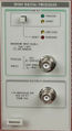
Tek dp501.jpg|Front Photo | |||
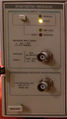
Tek dp501 on.jpg | |||
Tek dp501 cat.png|Catalog Entry | |||
Dp501 cat2.png|Catalog Entry | |||
Tek dm501 dividing 1.3ghz.jpg|DP501 dividing 1.3 GHz by 16 to get 81.2506 MHz | |||
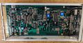
Tek dp501 internal1.jpg | |||
Tek dp501 internal2.jpg | |||
</gallery> | </gallery> | ||
[[Category:TM500 counter plugins]] | |||
Latest revision as of 05:02, 27 October 2023

The Tektronix DP501 is a 1.3 GHz ÷ 16 prescaler plug-in for the TM500 system.
It is specifically designed to interface with the DC503A, DC509, DC5009, DC510 and DC5010 Universal Counter Timers through the TM500 rear interface to make the counter display the correct frequency directly. For the DC503A this is done by routing the counter's reference clock to the DP501, where it is also divided by 16, and fed back to the counter as the new reference. For all other microprocessor based counters like the DC50(0)9 the correct frequency display is achieved by a dedicated prescaler signal.
The DP501 also contains the required logic to interface a TR502 tracking generator for accurate dot marker frequency measurements, effectively replacing a DC508 Option 7 .
Key Specifications
| Input Frequency | 100 MHz to ≥1.3 GHz |
|---|---|
| Sensitivity | ≤20 mVRMS (−21 dBm) from 100 MHz to 1 GHz; ≤30 mVRMS (−17 dBm) from 1 GHz to 1.3 GHz |
| Input Impedance | 50 Ω, AC coupled; VSWR ≤2.2 : 1 |
| Output | ≥200 mVp-p into 50 Ω, from a 50 Ω source |
| Max. Input | +20 dBm (damage level ≥ +25 dBm) |
| Power | 19 VA |
Rear Interface
- 14B - Prescale (14A GND)
- 15B - Ref Clk Input (15A GND)
- 21A - Div By 16 Ref Out (21B GND)
Links
Pictures
-
Front Photo
-
-
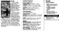
Catalog Entry
-
Catalog Entry
-

DP501 dividing 1.3 GHz by 16 to get 81.2506 MHz
-

-