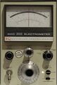
Keithley 610C

The Keithley 610C Solid State Electrometer can measure voltages (with a very high input resistance), very low currents, high resistances and charge. It is a solid-state successor to the all-tube Keithley 610 and tube/transistor Keithley 610B that had used electrometer tubes at the input.
Key Specifications
| Voltage | 1 mV to 100 V full scale in 11 ranges (×1/×3) |
|---|---|
| Input resistance (volts mode) | >1014 Ω or selectable 10 Ω to 1011 Ω in decade steps |
| Accuracy | 1% of full scale, noise 25 μV |
| Zero offset drift | <1 mV per day / 150 μV per °C |
| Current | 10–14 A to 0.3 A full scale in 28 ranges (×1/×3) |
| Resistance | 100 Ω to 1014 Ω full scale in 25 linear ranges (×1/×3) |
| Charge | 10–13 C to 10–3 C (Ampere-seconds) full scale in 17 ranges (×1/×3) |
| Display | Analog meter with mirror scale; positive, negative and center-zero display modes |
| Power | 105−125 V or 210−250 V, 50−60 Hz (some units labelled 50−1000 Hz), 10 W |
| Accessories |
|
The unit has two sets of outputs on the back panel — one to attach a DVM or recorder, with ±3 V or ±1 mA full scale, using an Amphenol 80-PC2F connector, the other output (marked "×1") tracks the input voltage (in "Normal" mode only, s.b.). It is therefore possible to use the 610C as an amplifier, with a bandwidth of 40 kHz at ×1 down to 100 Hz at maximum amplification.
The input connector is a PL-259 ("UHF") socket. Newer electrometers use triaxial input connectors, with the inner shield (guard) driven by an amplifier to be at the same potential as the input, in order to minimize leakage currents. It is possible to use a guarded input connection on the 610C through an adapter, although the guard potential is only available on the back of the instrument, at the "× 1" output. (The terminal labelled "guard" is at input ground potential.)
Measurement Principle
When set to the "Normal" feedback mode, the 610C measures an input voltage, or an input current as the voltage drop across a shunt resistor. The large range switch selects the shunt resistance in decade steps between 10 Ω and 1011 Ω, or leaves the input open.
Because only the input voltage is measured, the shunts can also be used as defined input resistances in Volts mode (1 / current range). For example, in the 1 nA (10-9 A) range, a 1 GΩ resistance is connected across the input.
Note that in Normal mode, the "×1" output on the rear follows the input voltage within the full range, i.e. when the input is at +100 V, so is that output (for loads ≤100 μA).
In "Fast" feedback mode, the current range resistor is connected between the amplifier output and the input, turning the instrument into a feedback amperemeter (transimpedance amplifier) and reducing the input voltage burden to less than 100 μV. (Modern pico/nanoamperemeters work this way.)
Because there is very little (change of) input voltage, the meter's input capacitance has no effect, and the meter responds faster, hence the name.
In the Coulomb ranges (only valid in Fast mode), a capacitor takes the place of the feedback resistor, the instrument integrates input currents and thereby measures charge in Ampere-seconds (Coulombs).
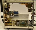
Internals
At the core of the 610C is an operational amplifier with MOSFET inputs that is constructed from discrete transistors and has a ±100 V range for input and output voltages. This is done by bootstrapping – the output stage operates on ±120 V supplies, and the actual amplifier uses a floating ±9 V supply referred to that output. As a result, the instrument can measure voltages of up to 100 V in either polarity without needing a resistive input divider, thereby preserving the MOSFET gate's high input resistance of >1014 Ω over the entire ±100 V input range.
The opamp has a three-level zero adjustment, with switches for coarse (at the rear panel) and medium levels, and a 10-turn potentiometer for fine nulling. Zero drift is fairly low once warmed up, especially compared to the predecessor units like the Keithley 610B which still relied on electrometer vacuum tubes in the input stage.
The 610C contains only 10 transistors and 2 MOSFETs altogether, which are all used for amplification. The power supply is regulated using Zener diodes.
Links
- Keithley 610C Electrometer teardown @ YouTube
- Keithley 610C Electrometer Repair @ YouTube
- Keithley 610C Electrometer Calibration and Experiments @ YouTube
- Keithley 610C Electrometer @ radiomuseum.org
Pictures
-
-
-
-
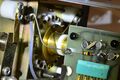
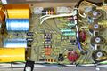
Input stage: MOSFETS are thermally coupled, input signal is routed over the top of the circuit board using teflon standoffs
-
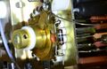
Range selector switch with teflon-insulated contacts
-
Range resistors, from 10 Ω to 1011 Ω
-
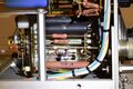
Output stage and power supply


