MicroLab I

From TekWiki
Jump to navigation Jump to search
Tektronix MicroLab I
Microprocessor development kit
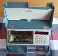
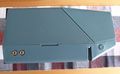
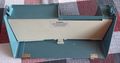
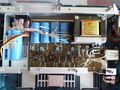
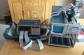
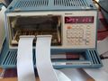
MicroLab 1, opened

Produced from (?) to (?)

Manuals
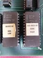
ROM/PLD Images
File Pos. Checksum
160-0223-00.bin U5010 fad5deb5

(Manuals are OCRed PDF files unless noted otherwise)

Manuals – Specifications – Links – Pictures

The Tektronix MicroLab I (part number 067-0892-xx) is a microprocessor development tool.

The manual says,

The MicroLab I is a tool used to test and demonstrate microprocessor/microcomputer development systems.

The MicroLab I can be “personalized” to act like any of a number of microprocessor- or microcomputer-based computers.

The MicroLab I is designed to take the place of prototype equipment in an environment where a microprocessor development system is demonstrated or tested.

The functions of the MicroLab I are:

  • to test an Emulator Processor and its Prototype Control Probe
  • to demonstrate the use of an Emulator Processor, and at the same time, a microprocessor development system

The MicroLab I mainframe contains the general interface logic (including I/O ports, RAM, keyboard and display) used by all the personality cards.

With some personality cards, the MicroLab I is capable of operating on a stand-alone basis. When the personality card is installed, and a microprocessor or microcomputer is installed in the personality card, the MicroLab I becomes a complete mini-computer.

In combination with the 067-0911-00 diagnostic interface, it is part of the 7854 digital diagnostic system.

Variants

Part number Variant
067-0892-00 North American 120 V version
067-0892-01 Universal European 220 V version
067-0892-02 UK 240 V version
067-0892-03 Australian 240 V version
067-0892-04 North American 240 V version

An expansion port is present on some but not all units. It is unclear if this was a separate version of the device.

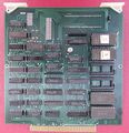
Personality Modules

Personality modules came with supplementary manuals specifically outlining operation of the respective card.

Part number Description Manual
018-0144-00 RCA 1802 personality card
018-0145-00 Fairchild F8 personality card
018-0146-00 Intel 8085A personality card 070-2850-00
018-0147-00 Fairchild 3870/3872 personality card 070-2862-01
018-0151-00 Motorola 6800/6802/6808 personality card 070-2939-01
018-0152-00 MCS48 8002A support personality card 070-2937-01
018-0152-01 MCS48 8550 support personality card 070-2937-01
018-0153-00 6500/1 8002A personality card 070-2941-01
018-0153-01 6500/1 8550 personality card 070-2941-01
018-0154-00 6801 / 68120 personality card 070-3983-00
018-0156-00 Zilog Z80A personality card 070-2861-01
018-0156-01 Zilog Z80B personality card 070-2861-01
018-0157-00 Motorola 6809 personality card 070-3984-00
018-0171-00 Zilog Z8000 personality card 070-2863-00
018-0172-00 Intel 8086/8088 personality card 070-2865-00
018-0179-00 Texas Instruments TMS9900/9989 personality card 070-4362-00
018-0180-00 Motorola 68000 personality card 070-3982-00
018-0190-00 Motorola 6809E personality card 070-4460-00
018-0206-00 Motorola 68xxx personality card 070-4869-00
018-0207-00 National Semiconductor NSC800 personality card
018-0210-00 7807/7809/7810/7811/7816 personality card

Links

Operation

Each personality card has a basic monitor program in EPROM.

Operation is generally the same for all personality cards, although opcodes change with CPU. When the MicroLab is turned on, the screen will display the detected personality card, and then display "Hello".

Using the keypad on the front, an operator can navigate through memory addresses displayed on the left-hand side of the display. The value is displayed on the right. When looking at a value, the INC and DEC keys can be used to increment and decrement the pointer, while the LOAD ADDRESS key allows the user to jump to a certain address. Once a suitable location is selected, the LOAD DATA key allows the operator to input a value in hexadecimal notation, however this can be slow.

Hitting the AUTO key enters Auto mode, in which entering a value for an address will increment to the next address and prompt for a value. To leave Auto mode, the operator can hit the SHIFT key. Almost all operations can be stopped/canceled using the SHIFT key. One can write a program this way, entering opcodes valid for the CPU's instruction set. The service manual outlines a simple adder for the 8050 personality card. To run a program, the GO key will start the program at the selected address. Program execution can only be interrupted by hitting the RESET key, which resets the MicroLab to the on-boot state. The SHIFT key doesn't only interrupt AUTO mode. If nothing is actively being done, hitting the SHIFT key will display a blank screen. Hitting a key 0-F will perform the action in orange text above the key – for example, SHIFT+0 will perform a self-test.

Display

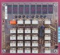
The MicroLab I has an eight-digit, 7-segment display which is self-refreshing. A PROM decodes all hexadecimal values.

Cassette Interface

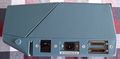
The cassette interface on the left-hand side of the unit is made up of two audio jacks. Any cassette player can be used to store data from the MicroLab. When the MicroLab is on, SHIFT+3 will prompt for a filename. Once a 2-character filename has been input as well as the start and end address, it will be saved to the cassette via KCS. The filename is required to load the file again – pressing SHIFT+2 will prompt for a file and then search the cassette until the file is found and loaded.

Serial Ports

On the lower left-hand side of the motherboard there is a row of jumper pins which control the baud rate. Only the terminal port is used by the unit. The modem port does nothing but can be accessed through programs on the chip. Only 9 pins on the modem port are populated, implying that the modem port could have been DB-9. The same can be said for the Terminal port, only 9 pins are populated, meaning they do not follow standard EIA RS-232 pinouts.

Breakpoint logic

The MicroLab I contains breakpoint circuitry that is used by some personality cards during the self-test and the processor tests. The breakpoint circuitry generates an interrupt when

  • a 16-bit address generated by the personality card matches an address stored in breakpoint circuitry (additionally, it can detect whether the address is a memory or I/O address, and whether it is read or written);
  • or when a pattern of six of the 21 available processor-dependent lines from the personality card matches a pattern stored in the breakpoint circuitry.

Pictures

7854 diagnostic interface 067-0911-00

The diagnostic system of the 7854 consists of the 067-0911-00 diagnostic test interface, the 067-0961-00 diagnostics ROM, the MicroLab I and the 070-2972-YY signature tables. An RS-232 compatible terminal and a signature analyzer are also needed.

Components

Some Parts Used in the MicroLab I

Part Part Number(s) Class Description Used in
2114 SRAM 156-1028-00 156-1461-00 Monolithic integrated circuit 1K×4 SRAM 1980 5D10 MicroLab I Keithley 220
IM5610 Monolithic integrated circuit 32×8 (256 bit) PROM 7912AD MicroLab I SA501
Motorola 6850 156-0658-00 156-0658-01 Monolithic integrated circuit serial interface controller 021-0188-00 4041 4663 7250 MicroLab I

Trivia

The Microlab features a chassis similar to the 834 which uses circuitry similar to the 018-0156-00 Z80 personality board