PS503A/Repairs
Jump to navigation
Jump to search
- Tektronix PS503 and PS503A Dual Power Supply Repairs by Bob Haas, VintageTEK Museum @ YouTube
- Tektronix PS503A Power Supply Restoration by NFM @ YouTube
PS503A Manual
There are errors in the circuit drawing:
- All amplifiers are connected to +5 V or –5 V. In fact they are connected to the +6.2 V or –6.2 V supply.
- R48 is missing on the grid location table. It is in F1.
- Other parts are missing on the grid location table (Q25, ...)
PS503A: Instable Output/Output voltage is decreasing with time
Problem: The output is instable (±100 mV) and is decreasing with time. Both output channels behave symmetrically.
Solution: The faulty part was C34 (4.7 µF/50 V). C34 stabilises the reference voltage. Measuring C34 with an RLC-meter shows no fault: 5.0 µF and a series resistance of 5 Ω. The faulty behaviour of C34 can only be seen by applying a DC voltage (see picture).
C34 is shorted by the output-on button. So, replacing C34 with a tantalum capacitor is not recommended.
PS503A: Replacing the voltage indicator light bulb with a LED
To preserve the effect that the indicator lights up with higher output voltage, some resistor have to be changed.
- R48 (+ output) and R148 (– output) limits the low current that will always flow when the output is ON. This current will flow at 0 V output voltage. (supplied by +33 V / –33 V)
- R55 (+ output) and R155 (– output) limits the high current that will be added to the low current according to the output voltage. (supplied by the 0 to 20 V output voltage)
- The LED should be pushed as deep as possible into the bulb holder, so it holds the yellow plastic window part in place.
- Choose R48/R148 and R55/R155 according the chosen LED (LED current and power dissipation of the resistor)
- R48 is missing on the grid location table. It is in F1.
Pictures
-
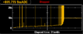
DC current thru a faulty C34 (12 V / 10 mA limit)
