Uploads by Bo
Jump to navigation
Jump to search
This special page shows all uploaded files.
| Date | Name | Thumbnail | Size | Description | Versions |
|---|---|---|---|---|---|
| 07:10, 17 May 2024 | Telequipment D56 manual ocr.pdf (file) |  |
32.13 MB | Scanned old xerox manual in 300dpi with ocr including some old notes | 1 |
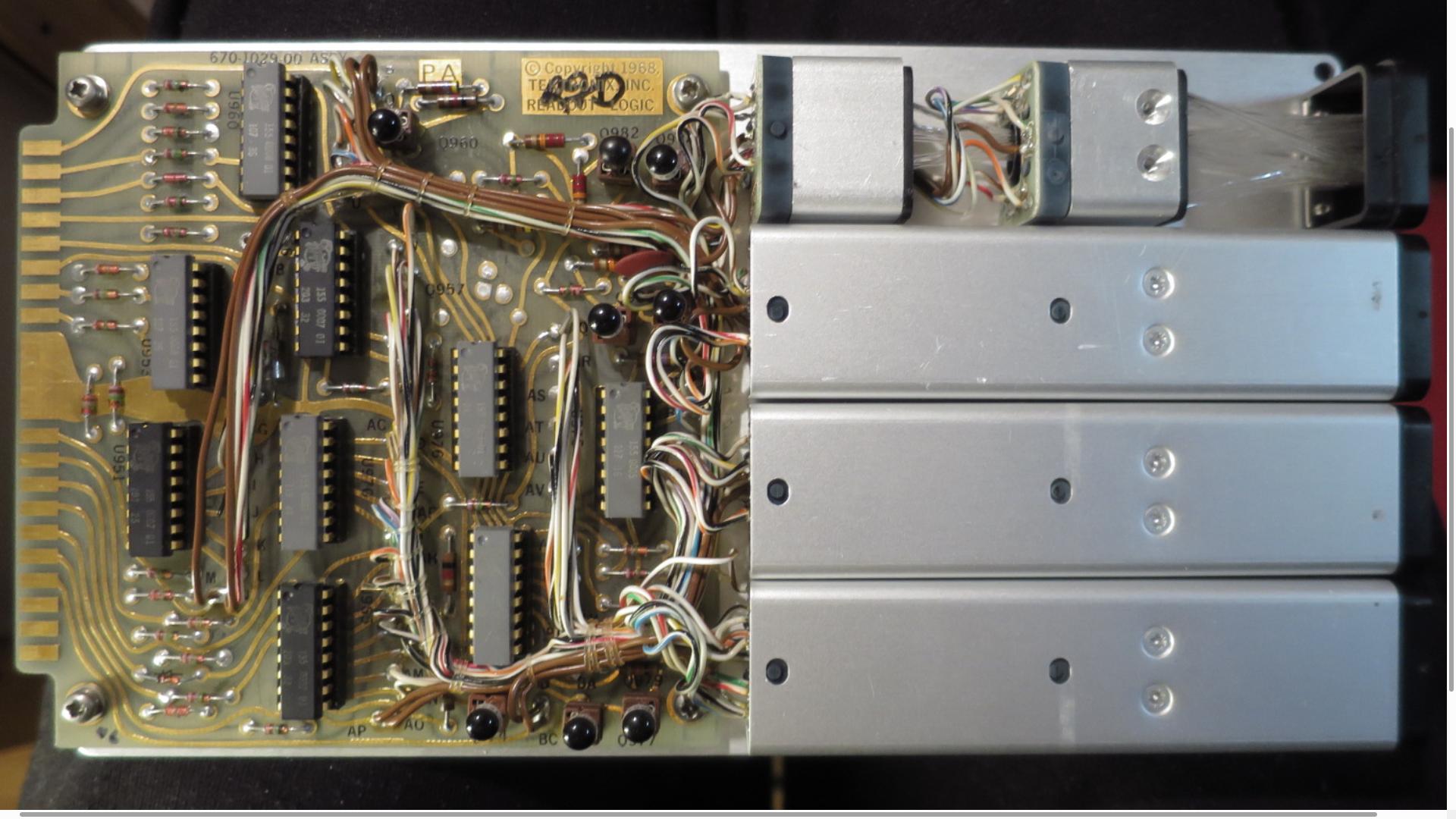
| 13:36, 14 February 2024 | Tek576 Readout 20240213.jpg (file) |  |
223 KB | Tektronix 576 Readout using IC-sockets for the custom Tektronix IC's. One section is open to show the thin light tubes. Quite tricky to change the light bulbs. I was warned about using LED's as they have different color and diffusion. | 1 |
| 12:39, 12 February 2024 | 20 TQD56 PC25 20240212.jpg (file) |  |
102 KB | * A board with mostly capacitors after the Vertical Amplifiers, with the tubes to the right. * The TO-3 transistor is here seen on the left side. This transistor is probably part of a DC-regulator at the rear side board. | 1 |
| 12:36, 12 February 2024 | 19 TQD56 Vertical 20240212.jpg (file) |  |
137 KB | * The Vertical Amplifiers seen from bottom side with tubes on the other and input switches to the right. | 1 |
| 12:25, 12 February 2024 | 17 TQD56 Trimmer A 20240212.jpg (file) |  |
103 KB | * Warning! * Do not touch or bend the two red wires with open ends that seems oddly forgotten. * They are part of a trim capacitor that are used to compensate for the Time Base Amplifiers frequency response. One pair at the upper board and one pair at the lower board. If you change the tube to an other manufacturer, it may be needed to adjust (bend) a little. Nothing is mentioned in the D55A manual what I could find. | 1 |
| 12:15, 12 February 2024 | 16 TQD56 Motorola T119 20240212.jpg (file) |  |
97 KB | Here are two more Motorola T-119 PNP transistors, two in each board for A and B Time Base. This is a small board with one tube, V109 - ECF80. Possibly the trigger board? | 1 |
| 12:11, 12 February 2024 | 15 TQD56 Front PC26 20240212.jpg (file) |  |
92 KB | Two Motorola T-119 PNP transistors in the time delay circuitry near the front panel on board PC26. The 10 turn variable resistor on the front is connected here. I have not been able to find data on these transistors. | 1 |
| 09:40, 12 February 2024 | 13 TQD56 PC27 20240212.jpg (file) |  |
107 KB | Trace Blanking Board PC27 Closeup (rotated CCV so top is now left) | 1 |
| 09:36, 12 February 2024 | 12 TQD56 Timebase A 20240212.jpg (file) |  |
245 KB | Timebast A Closeup | 1 |
| 09:35, 12 February 2024 | 11 TQD56 Side Timebase 20240212.jpg (file) |  |
179 KB | Timebase Side View. Two identical Timebase boards top and bottom with Time Delay board in the middle. Top Rear Trace Blanking Board and below High Voltage Capacitors. | 1 |
| 09:32, 12 February 2024 | 10 TQD56 Rear closeup 20240212.jpg (file) |  |
132 KB | Rear View Closeup | 1 |
| 09:22, 12 February 2024 | 09 TQD56 Rear regulators 20240212.jpg (file) |  |
75 KB | Rear View with cover removed. Two Transformers at the bottom. Mains Voltage Setting in the center with Fuse and Mains Cable left and Z-axis input right. Regulator board PC24 to the left. CRT socket high right. TO-3 transistor solder pins visible under the CRT. Regulator board PC23 to the right. | 1 |
| 09:14, 12 February 2024 | 08 TQD56 Vertical Amplifiers 20240212.jpg (file) |  |
111 KB | Closeup of CRT and Vertical Amplifiers. One TO-3 Transistor is barely visible on the left panel. Red CRT HV cable, 6 kV. | 1 |
| 09:10, 12 February 2024 | 07 TQD56 Side Vertical 20240212.jpg (file) |  |
122 KB | Side view of Vertical Amplifiers with cover removed. | 1 |
| 08:44, 12 February 2024 | 05 TQD56 Rear Cover 20240211.jpg (file) |  |
89 KB | Rear View. The serial number is 577, hard to read even by the naked eye as it is stamped into the metal. | 1 |
| 08:40, 12 February 2024 | 04 TQD56 Running 20240211.jpg (file) |  |
81 KB | Both channels running on Timebase A. After this picture, channel 1 stopped "sweeping", so no better picture available now. | 1 |
| 08:32, 12 February 2024 | 01 TQD56 Front 20240212.jpg (file) |  |
74 KB | Telequipment D56 Front View | 1 |